


frogblue AG, Luxemburger Straße 6, 67657 Kaiserslautern, Germany — Tel. + 49-631-520829-120 — info@frogblue.com
frogblue TECHNOLOGY GmbH, Luxemburger Straße 6, 67657 Kaiserslautern, Germany — Tel. +49-631-520829-0 — info@frogblue-tec.com
Note: Reprinting and photomechanical reproduction are only permitted with our express permission. The printed products issued by frogblue AG provide information to the best of our knowledge, but any statements made are not legally binding. All illustrations and photographs of the products shown are not binding regarding color, dimensions, and equipment. We reserve the right to make changes and updates in the interests of progress.
Kaiserslautern, 05 July 2023 — Made in Germany
1 About this manual
Read this manual carefully and follow the instructions provided. This will prevent personal injury and damage to property and ensure reliable operation as well as the long service life of the equipment.
Keep the manual in a safe place.
If you pass on devices for others to use, include this manual.
frogblue AG accepts no liability for damage caused by non-observance of this manual.
If you require further information or have questions about the devices, please contact frogblue AG or visit us on the internet at → frogblue.com.
This manual describes how to set up and configure smart home applications quickly and easily with frogblue. You will learn:
- ✓ how to plan a smart home application with Frogs,
- ✓ how to install Frogs,
- ✓ how to configure and manage a frogblue system with the frogProject app.
1.1 Who is this manual for?
This manual is intended for electricians and anyone who wishes to plan, configure, and manage smart home applications.
Installation, commissioning, and maintenance of the devices may only be carried out by trained electricians with appropriate qualifications.
1.2 Typographical conventions
The following typographical conventions are used in this manual:
| Example | Meaning |
|---|---|
Command |
A command or code is shown in Courier. |
| Screen text | Text that is visible in the user interface is marked in bold. |
| Reference | References are marked in italics. |
1.3 Abbreviations
| Abbreviation | Meaning |
|---|---|
| Bluetooth LE | Bluetooth Low Energy |
| KNX | Fieldbus for building automation |
| MAC address | Media Access Control Address |
| VPN | Virtual Private Network |
| WLAN | Wireless Local Area Network |
2 frogblue – Introduction and overview
Decentralized Bluetooth® network with automatic configuration
frogblue devices are connected to the mains and use wireless Bluetooth® technology to transmit switching commands and data. You therefore do not require any special cables, IT infrastructure or Internet. Communication with smartphones and tablets takes place directly via Bluetooth® without additional devices. frogblue guarantees the highest possible data security based on double encryption of the data, because in addition to the Bluetooth® encryption the frogblue data is also coded a second time (128-bit rollover).
The frogblue system is fail-safe, as the decentralized intelligence means a central unit for function control and communication is not necessary. If two units are outside the Bluetooth® range, any frogblue devices in between will forward messages. For users and installers, this happens automatically and without programming. The switching commands or data information automatically find their way in the frogblue network.
If the frogblue devices are controlled remotely via the frogProject app; this is realized by means of a secured VPN connection via the Internet to an in-house frogblue display (via WLAN connection). The double encryption and the VPN connection and frogblue messages guarantee a very high level of data security.
Configuration via naming of messages
The connection between switching inputs and switching outputs (for example between a photoelectric proximity switch and a lamp) is made by naming messages assigned to the inputs or outputs in the frogProject app. If the message for the switching input as well as for the switching output has the same name (for example “Kitchen light”), this establishes the connection between the two devices and their inputs or outputs. If another output with the same name (here “kitchen light”) is on an additional device, both outputs will be virtually connected to each other and will switch synchronously.
The same applies to other inputs with the same name, so that multi-way switching is easy to realize with multiple light sensors. Switching inputs and outputs can be allocated as desired. The linking and message transmission to the switch take place automatically without further configuration.
Typing and space-based switching operations
By typing inputs and outputs and the space-based configuration of the devices, it is possible minimize the effort involved in configuration. To do this, the individual frogblue devices are allocated to a room (for example “Living room”), and their inputs and outputs are typed, which means an output may be marked as a light or roller shutter control or an input may be marked as a light sensor. Accordingly, these devices are automatically linked by way of the tying switching command “light on in the living room” without further configuration and without name assignment of the inputs and outputs. It does not matter how many devices or inputs and outputs there are in a room.
Such a typing switching command “light on in living room” can be put on any switching input of frogblue devices to switch on the light in that room or start the shadowing from another location, without knowing the number of devices and switching outputs in that room.
Parameterization of switching signals
All switching outputs can be parameterized individually and very specifically. So, amongst other things, the duty cycle, soft starts, dimming characteristics, delayed switching on and off and much more can be configured. The switching inputs can also be parameterized in such a way that, for example, a different duty cycle or brightness of the lamp can be realized depending on the switch.
Overlay of switching signals
Inputs and outputs can have multiple names and as such trigger different switching operations or actions. A light sensor can therefore switch on the living and dining room lights simultaneously and send different messages with different parameters depending on the button touch (short, long, double-click etc.). The overlay of messages to the outputs can allow convenient scenery control or the signaling of incidents, such as the kitchen light blinking when the doorbell rings.
System-wide functions through macros
For the simple configuration of central commands, such as central switching of multiple lamps, macros can be defined and assigned to the devices. If, for example, the central input (central control command for light) on all switches be converted from “double-click” to a “triple click”, this only needs to be changed in one place, which is the macro. These macro functions ensure a clear configuration and significantly reduce the configuration effort.
Time control
All frogblue units have time functions for switching. Lamps or roller shutters can be controlled decentral by the devices themselves by way of a weekly schedule. This means that a central unit is not necessary. The time in the individual frogblue modules is synchronized via the Bluetooth® network with special frogblue devices with battery-buffered clocks or GPS time receivers. The frogblue display can as an option be supplied with the current time via its WLAN interface from a time server on the Internet.
This automatic time synchronization via the Bluetooth® network ensures that even after a power failure in all devices, the current time is again available within seconds. Of course, this time synchronization via the frogblue network is encrypted in addition to the Bluetooth® and therefore offers the highest possible security against manipulators.
Logic module decentralized in all devices
In every frogblue device, input and output signals of other frogblue devices can be linked system-wide. So, for example, a lamp can be switched on in addition to the normal operation by overlay for as long as a door is open (once a door contact signals this to a frogblue input module). The logic linking of multiple signals, including together with time conditions or a weekly schedule, is possible and is done decentral in the frogblue devices.
The typing of input signals with attributes, such as window contact, brightness sensor or frost monitor, allows fast implementation of sophisticated logic and control functions. With these functions for example, a children’s room lamp can be limited to 30% of the maximum rating or an alarm can only be triggered by open doors on weekends.
Data backup of all data in one file
The entire project configuration of all data, therefore both the configuration data of all frogblue units and the settings on the frogProject app, such as passwords and project data, are stored in a single system backup. This system backup can be secured in every single frogblue unit and sent by email. This means that all data of a frogblue installation are stored in only one file.
A system function signals the end user via the display, and if applicable the frogProject app, that they are in possession of all the necessary configuration data for their frogblue system. This ensures that the system configuration is available for maintenance by third parties at any time, even if the electrician cannot be reached. The end user also needs the associated project password of course.
Platform-independent on Android, iOS, and Windows
The frogblue software runs on Android, iOS, and Windows. The end user app (frogControl) is identical to the app on the frogDisplay, that is the end user only needs to be familiar with one control panel, regardless of whether they are using the display on site or the smartphone app.
2.1 Revolutionary simplicity – the functional principle
This is what you are accustomed to: after the electrician has connected a lamp, the lamp goes on as soon as the button is pressed. However, this does not allow automatic controls.

Figure: A connected lamp is switched on when a switch is actuated.
A Frog is connected to the circuit (in a flush-mounted box) to enable controls such as time control or central control.
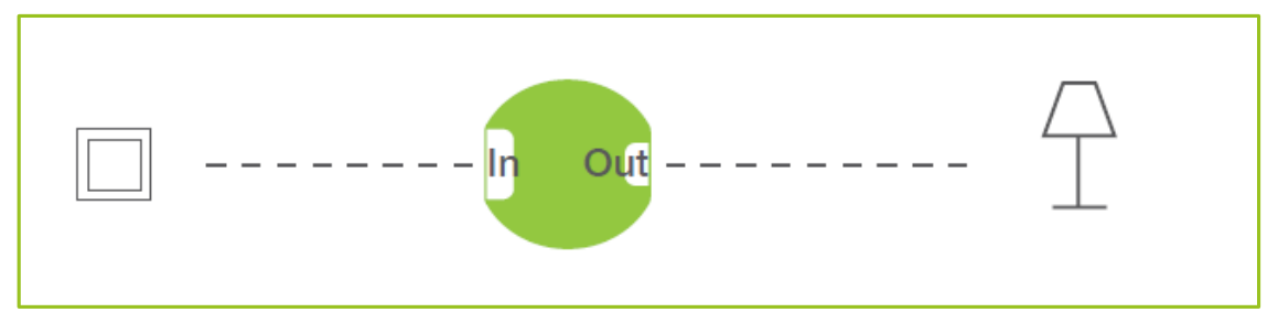
Figure: A Frog is connected to a circuit.
The button is connected to the input In, the lamp to the output Out. A text message is assigned to the input In via the frogProject app, for example LightOn. This is sent when the button is pressed. If the output Out knows the text message LightOn (also assigned there via the frogProject app), the lamp is switched on when the switch is pressed.

Figure: The Frog switches through when the text message in the input and output match.
If the Out output has been configured for another text message, for example for the text message Lights, the lamp remains off even if the switch is pressed.
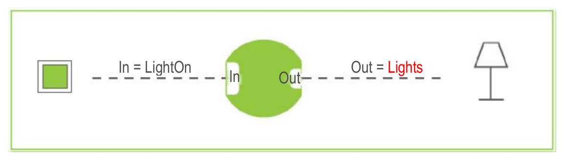
Figure: The Frog does not switch through if the text message in the input and output do not match.
If several Frogs are present in a building, all those frogs at whose output the text message LightOn has been configured will switch through. The Frogs receive the message LightOn via Bluetooth®, this is, they are not wired to each other. The message functions like a virtual cable that can be adapted at any time.
If different scenes are to be set up, several messages can be entered both at the output and at the input, for example to make the lamps light up differently.
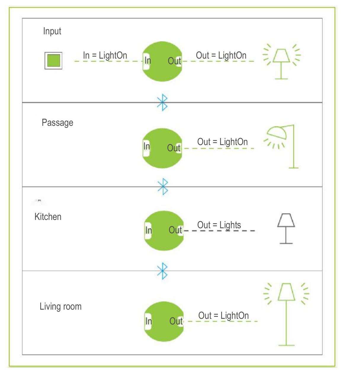
Figure: All Frogs that recognize the text message LightOn switch through.
In addition to activating switches, the sending of messages can also be controlled via logic functions.
2.2 frogblue software – an overview
The following frogblue software is available for controlling and configuring a frogblue system:
 With the frogProject app you can plan, configure, and control a frogblue system. This app provides you with all the features you need to create and manage both simple and sophisticated smart home applications.
You will find detailed information on how to use the frogProject app in this manual.
With the frogProject app you can plan, configure, and control a frogblue system. This app provides you with all the features you need to create and manage both simple and sophisticated smart home applications.
You will find detailed information on how to use the frogProject app in this manual.
 With the frogControl app you can easily control the frogblue units for a project set up and configured with the frogProject app.
You will find detailed information on how to use the frogProject app in the
→ frogControl User Manual.
With the frogControl app you can easily control the frogblue units for a project set up and configured with the frogProject app.
You will find detailed information on how to use the frogProject app in the
→ frogControl User Manual.
frogware: The software (firmware) ) in the Frogs and frogKeys, which contains the system configuration and controls the frogblue system. The frogware is downloaded along with the frogProject app and must be updated in the Frogs and frogKeys afterwards. Information on updating the frogware can be found in this manual in section → Updating frogware, page 155.
3 Safety: frogblue devices
The devices are built according to the currently valid rules of technology and are safe to operate. They are tested and leave the factory in a technically safe condition.
Nevertheless, there are residual risks. Read and follow the safety instructions to avoid hazards.
frogblue AG accepts no liability for damage caused by non-observance of safety instructions.
3.1 Notes and symbols used
The following information points out special dangers when handling the devices or provides useful indications:
 |
Danger — Danger to life/serious damage to health. The respective warning symbol in conjunction with the signal word Danger indicates an imminent danger that may lead to death or serious (irreversible) injury. |
 |
Warning — Severe damage to health. The respective warning symbol in conjunction with the signal word Warning indicates an impending danger which can lead to death or serious (irreversible) injury. |
|
Caution — Damage to health. The respective warning symbol in conjunction with the signal word Caution indicates a danger that can lead to minor (reversible) injuries. |
 |
Attention — Damage to property. This symbol in conjunction with the signal word Attention indicates a situation which may result in damage to the product itself or to objects in its vicinity. |
 |
This symbol warns of electrical voltage. |
Note The signal word Note indicates useful tips and recommendations for efficient handling of the product.
3.2 Intended use
The devices are Bluetooth® receivers and transmitters designed for flush-mounting. The devices form part of the frogblue system.
The devices are intended for the following:
- ✓ operation according to the technical data listed,
- ✓ installation in dry interiors and suitable flush-mounted boxes,
- ✓ use with the connection options available on the devices.
Intended use also includes compliance with all information in this manual.
3.3 Improper use
Any use which is not mentioned under → Intended use is considered to be contrary to the intended use and can lead to personal injury and damage to property.
frogblue AG is not liable for damages caused by improper use of the devices. The risk is borne solely by the user or operator.
The devices are not intended for the following:
- Unauthorized structural changes
- Repairs
- Outdoor use without appropriate protective housing
3.4 Safety instructions
4 Security: frogProject app – passwords
All device configurations of the frogblue devices are saved in the frogProject app in a project configuration with the help of a project file.
The project is protected by three passwords:
- ✓ project password
- ✓ device key
- ✓ random network key
Project password
The project password protects the project file on the tablet or laptop. A project file can only be imported to another device if the correct project password is entered. The project password is assigned by you when you create a project with the frogProject app.
Keep the project password in a safe place! You need the project password to restore a project or to transfer a project to another device.
Device key
The device key secures communication with the frogblue devices, that is accessing the Frogs with a tablet. Only with the device key can you change the device configuration. The device key is assigned automatically when you create a project on the frogProject app and is identical to the project password.
Keep the device key in a safe place! Only with a device key can you access to a Frog via Bluetooth®.
Project password and device key When you create a new project and therefore assign a project password to the project, a device key identical to the project password is automatically assigned. The project password can be shared with third parties, for example a technician who has configured the project. Once the project configuration is complete, you should change the device key to protect the device configuration in the Frogs from unauthorized access. After changing the device key, you can still configure the frogProject app on the tablet. However, the device configuration is always carried out using the device key.
Changing the project password and device key
You can change both the project password and the device key at a later stage. If the device key is changed, all frogblue devices must be updated.
Project password and device key have been lost
If the project password and the device key are no longer available, any frogblue device can be reset using a reset key. The reset key is always printed on the housing of the device and is only valid for that device.
Radom network key
The key for communication between the devices is randomly assigned when the project is created and can be reset if the device key is changed.
Note When devices are removed from the project, the key for the network should be reset.
5 Notes on environmental protection
 |
This symbol indicates that this product must not be disposed of with normal household waste in accordance with local laws. Please take your old electrical equipment to a designated collection point. |
 |
Batteries and rechargeable batteries must not be disposed of with household waste, but you are legally obliged to return used batteries and rechargeable batteries. Used batteries can contain harmful substances which, if not stored or disposed of properly, can harm the environment or your health. However, batteries also contain important raw materials such as iron, zinc, manganese, or nickel, which can be recycled. Please return the batteries free of charge after use in your immediate vicinity (for example in shops or municipal collection points). |
Handling batteries
Keep batteries away from children!
Remove batteries if they have gone flat or if the unit has not been used for an extended period of time.
If a battery has leaked, remove all batteries, and ensure that skin and clothing do not come into contact with the liquid.
Battery fluid is corrosive and may be toxic. If this happens, rinse the affected area thoroughly under running water. Use a slightly moistened paper towel to clean the unit. Only use batteries of the correct size and type.
The declarations of conformity according to CE marking for the products can be found below: → https://www.frogblue.com/de-de/support/downloads/
6 General wiring instructions
Installation, commissioning, and maintenance of the devices may only be carried out by trained electricians with appropriate qualifications.
The electrician must have read and understood the manual and follow the instructions.
The electrician must comply with the national regulations applicable in their country regarding the installation, functional testing, repair, and maintenance of electrical products.
The electrician must be familiar with and correctly apply the “Five Safety Rules” (DIN VDE 0105, EN 50110):
- Unlock
- Secure against restarting
- Determine the absence of voltage
- Grounding and short-circuiting
- Cover or barrier adjacent live parts.
In this chapter you will find information on:
VDE certifications — Information on VDE certifications. → VDE – Tested and certified, page 19.
Installation information — Frogs are connected in flush-mounted boxes. We recommend deep, ideally larger-sized flush-mounted boxes for new construction or renovation projects. Detailed information on the installation of a Frog can also be found in the enclosed operating instructions for the respective Frog. → Installation information, page 20
Wiring examples — Typical Frogs wiring examples in flush-mounted boxes are presented here. → Wiring examples, page 23.
Range of Frogs — The typical free field range for Frogs is about 30 meters. Inside a building, the range is up to 10 meters, depending on the structure of the building. In the case of influencing factors or greater distances, you can simply connect a Frog as a repeater in between. → Range of Frogs, page 29.
6.1 VDE – Tested and certified
The technical conformity of the product with the requirements of the harmonization regulations is demonstrated by the technical documentation and compliance with the following standards:
- DIN EN 60669-1 (VDE 0632 Part 1):2009-10; EN 60669-1:1999 + A1:2002 + A2:2008
- IEC 60669-1:1998 + IEC 60669-1:1998/AMD1:1999 + IEC 60669-1:1998/AMD2:2006
- Switches for household and similar fixed electrical installations – Part 1: General requirements
- DIN EN 60669-2-1 (VDE 0632-2-1):2010-03; EN 60669-2-1:2004 + A1:2009
- IEC 60669-2-1:2002 + IEC 60669-2-1:2002/AMD1:2008
- Switches for household and similar fixed electrical installations – Part 2-1: Particular requirements – Electronic switches
- DIN EN 60669-2-1/A12 (VDE 0632-2-1/A12) 2010-09; EN60669-2-1:2004/A12:2010
- Switches for household and similar fixed electrical installations – Part 2-1: Particular requirements – Electronic switches
- DIN EN 60669-2-5 (VDE 0632-2-5):2017-05; EN 60669-2-5:2016
- IEC 60669-2-5:2013
- Switches for household and similar fixed electrical installations – Part 2-5: Particular requirements – Switches and similar accessories for use in home and building electronic systems (ESHG)
- DIN EN 50428 (VDE 0632-400):2010-02; EN 50428:2005 + A1:2007 + A2:2009
- Switches for household and similar fixed electrical installations – Collateral standard – Switches and similar accessories for use in home and building electronic systems (ESHG)
Note Updates and additional information can be found on the website at → frogblue.com.
Note frogblue cannot guarantee that all LED lamps will work correctly due to the large number of manufacturers and lamp types. In particular, if non-dimmable lamps are connected to a dimmer, the lamps may not switch off completely.
6.2 Installation information
Frog are simply connected to the household power supply. Further cables or other wiring between the Frogs is not required.
We recommend using the Frogs with rigid conductors.
Note When planning, make sure that there is sufficient space for frogs and normal wiring. Choose sufficiently large flush-mounted boxes or provide sufficient space for the Frogs and the wiring.
If there is not enough space for Frogs and wiring, the following measures are recommended:
- ✓ Installation of Frogs behind a cavity wall.
- ✓ Provision of a second multiple-unit flush-mounted box. For example, an unused chamber of a multiple-unit flush-mounted box can be used as a socket.
- ✓ Use of larger flush-mounted boxes with an additional side connection space. Use the → flush-mounted boxes for new construction or renovation projects, as presented in the next section.
- ✓ Install the Frog behind a lamp or behind a suspended ceiling.
Reset key On each Frog, a reset key is printed on the back of each Frog. Make a note of the reset keys of all frogs before installing them and keep the reset keys in a safe place. You can use a reset key to reset a Frog if necessary. For information on resetting Frogs, see section → Resetting a frog, page 122.
6.2.1 Flush-mounted boxes
Note When selecting the flush-mounted box, make sure that there is sufficient space for the Frog and the normal wiring.
Boxes for flush mounting
| → f-tronic GmbH: Flush-mounted box, solid, 2-unit, Type: UP20 |  |
| → f-tronic GmbH: Flush-mounted box, solid, 3-unit, Type: UP30 |  |
| → f-tronic GmbH: Flush-mounted box, solid, 4-unit, Type: UP40 |  |
Boxes for mounting in hollow walls
For installation in hollow walls, we recommend the following combinations of two, three or four boxes, since they offer more space for the Frog and the wiring:
| → f-tronic GmbH: Hollow wall box, solid, 2-unit, Type: HW20 | 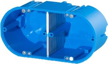 |
| → f-tronic GmbH: Hollow wall box, solid, 3-unit, Type: HW30 | 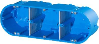 |
| → f-tronic GmbH: Hollow wall box, solid, 4-unit, Type: HW40 | 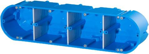 |
Flush-mounted boxes for new construction or renovation projects
For new construction or renovation projects, we recommend the following larger-sized flush-mounted boxes for more convenient installation of Frogs:
| → KAISER GmbH & Co. KG: Electronic box ECON® Flex | 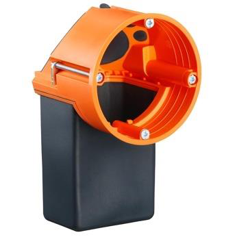 |
| → KAISER GmbH & Co. KG: Electronic box |  |
6.3 Wiring examples
The following examples show how a Frog and the wiring are distributed in the corresponding flush-mounted box. It is often advisable to use larger flush-mounted boxes than the wiring logic would require. This guarantees you greater flexibility so that the frogblue system can be expanded even after the planning phase has been completed.
6.3.1 frogIn3-AC in 2-unit flush-mounted box
The following circuit diagram shows the wiring of a frogIn3-AC is located in a 2-unit flush-mounted box.
In the lower chamber of the 2-unit flush-mounted box, the voltage is connected through.
The frogIn3-AC is located in the chamber of the 2-unit flush-mounted box.
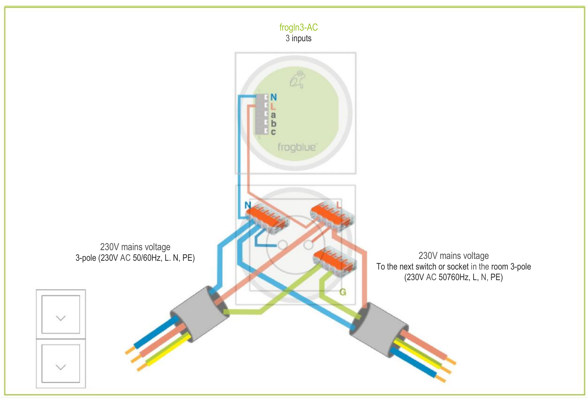
Figure: Wiring of a frogIn3-AC in a 2-unit flush-mounted box.
The following is suitable as a 2-unit flush-mounted box: → f-tronic GmbH: Flush-mounted box, solid, 2-unit, Type: UP20.
Figure: f-tronic GmbH: Flush-mounted box solid, 2-unit, type: UP20.
6.3.2 frogDim1-3 in 2-unit flush-mounted box
The following circuit diagram shows the wiring of a frogDim1-3 in a 2-unit flush-mounted box.
In the lower chamber of the 2-unit flush-mounted box, the voltage is connected through.
The frogDim1-3 is located in the upper chamber of the 2-unit flush-mounted box.

Figure: Wiring of a frogDim1-3 in a 2-unit flush-mounted box.
The following is suitable as a 2-unit flush-mounted box: → f-tronic GmbH: Flush-mounted box, solid, 2-unit, Type: UP20.
Figure: Flush-mounted box solid, 2-unit, type: UP20.
Also a 3-unit flush-mounted box such as the → f-tronic GmbH: Flush-mounted box solid, 3-unit, type: UP30 could be used to ensure that there is sufficient space for the Frog and the wiring as soon as the connections of the frogDim1-3 are to be wired.
6.3.3 frogDim1-3 with connected lamp
The following circuit diagram shows the wiring of a frogDim1-3 in a 3-unit flush-mounted box.
In the lower chamber of the 3-unit flush-mounted box, the voltage is connected through.
The frogDim1-3 is located in the middle chamber of the 3-unit flush-mounted box.
The wiring to the branch circuit is located in the upper chamber of the 3-unit flush-mounted box.
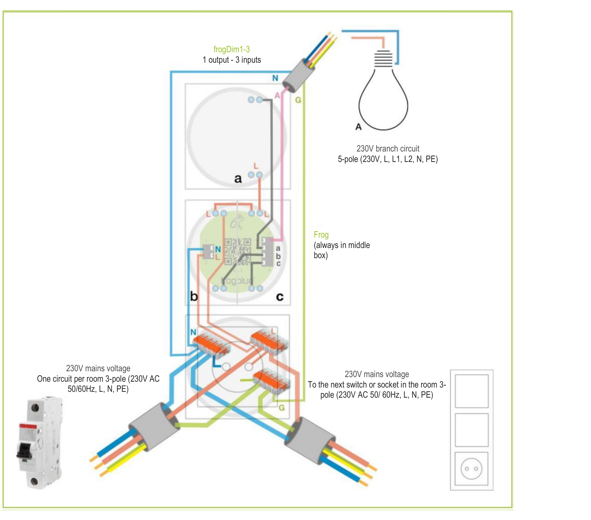
Figure: Wiring of a frogDim1-3 in a 3-unit flush-mounted box.
The following is suitable as a 3-unit flush-mounted box: → f-tronic GmbH: Flush-mounted box, solid, 3-unit, Type: UP30.
Figure: Flush-mounted box solid, 3-unit, type: UP30.
6.3.4 frogDim2-2 with two connected lamps
The following circuit diagram shows the wiring of a frogDim2-2 in a 3-unit flush-mounted box.
In the lower chamber of the 3-unit flush-mounted box, the voltage is connected through.
The frogDim2-2 is located in the middle chamber of the 3-unit flush-mounted box.
The wiring to the branch circuit is located in the upper chamber of the 3-unit flush-mounted box.

Figure: Wiring of a frogDim2-2 in a 3-unit flush-mounted box.
In addition to the 3-unit flush-mounted box such as the → f-tronic GmbH: Flush-mounted box solid, 3-unit, type: UP30, a 4-unit flush-mounted box such as the → f-tronic GmbH: Flush-mounted box solid, 4-unit, type: UP40 would also be suitable so as to ensure that there is sufficient space for the Frog and the cabling.
Figure: Flush-mounted box solid, 4-unit, type: UP40.
6.3.5 Bedroom scenario
The following diagram shows how different electronic devices in a bedroom can be controlled with Frogs.
When planning, make sure that there is sufficient space for the Frogs and for the wiring by means of deeper flush-mounted boxes or flush-mounted boxes with an additional lateral connection space.

Figure: Wiring for one bedroom to control several lamps and electronic devices.
The following circuits are shown:
- yellow/orange: Basic circuit.
- blue: Window circuit.
- red: Emergency power, can be connected to the yellow/orange circuit (optional). If the basic circuit fails, the emergency power supplies the display so that the frogblue system can still be operated. In addition, the frogContact5 and the frogMotion remain supplied with power, so the functions of the motion detector and alarm system remain guaranteed.
6.3.6 Bathroom scenario
The following diagram shows how different electronic devices in a bathroom can be controlled with Frogs.
When planning, make sure that there is sufficient space for the Frogs and for the wiring by means of deeper flush-mounted boxes or flush-mounted boxes with an additional lateral connection space.
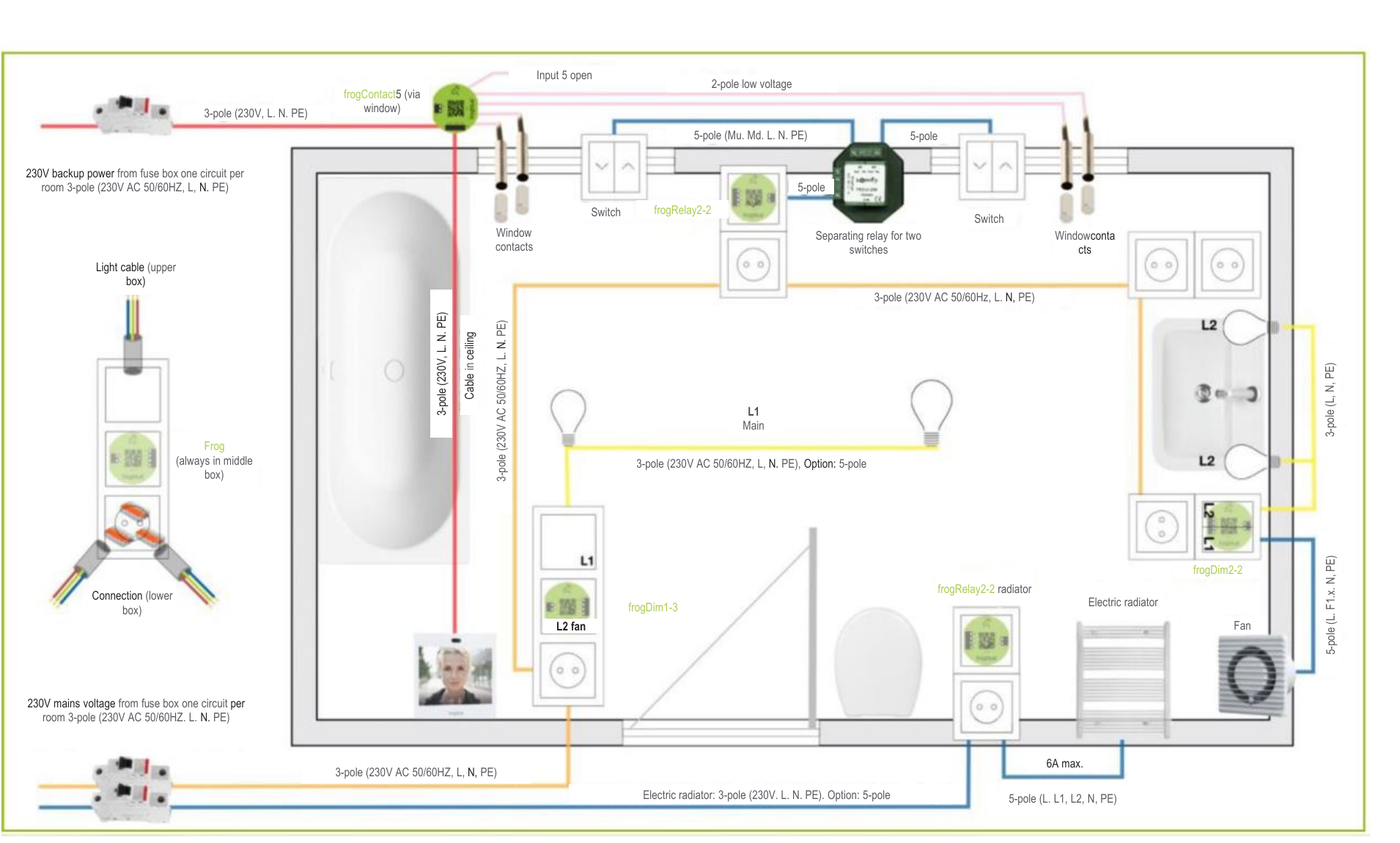
Figure: Wiring for a bathroom to control several lamps and electronic devices.
The following circuits are shown:
- yellow/orange: Basic circuit.
- blue: Window and heating circuit.
- red: Emergency power, can be connected to the yellow/orange circuit (optional). If the basic circuit fails, the emergency power supplies the display so that the frogblue system can still be operated. In addition, the frogContact5 remains supplied with power, so the function of the alarm system remains guaranteed.
6.4 Range of Frogs
Frogs communicate with each other via Bluetooth®. The typical free field range for Frogs is about 30 meters.
The range essentially depends on which building materials have been used and which sources of interference are present. Typical sources of interference for Bluetooth® are microwaves, LCD displays or wireless loudspeakers. Devices operating within a bandwidth between 2.4 GHz and 5 GHz are often responsible for a disturbed Bluetooth® connection.
To ensure a secure Bluetooth® connection between the Frogs, the recommendation is to measure the Bluetooth® field strength via the tablet and, if necessary, connect a Frog as a repeater in between. The field strength is displayed in the frogProject app.
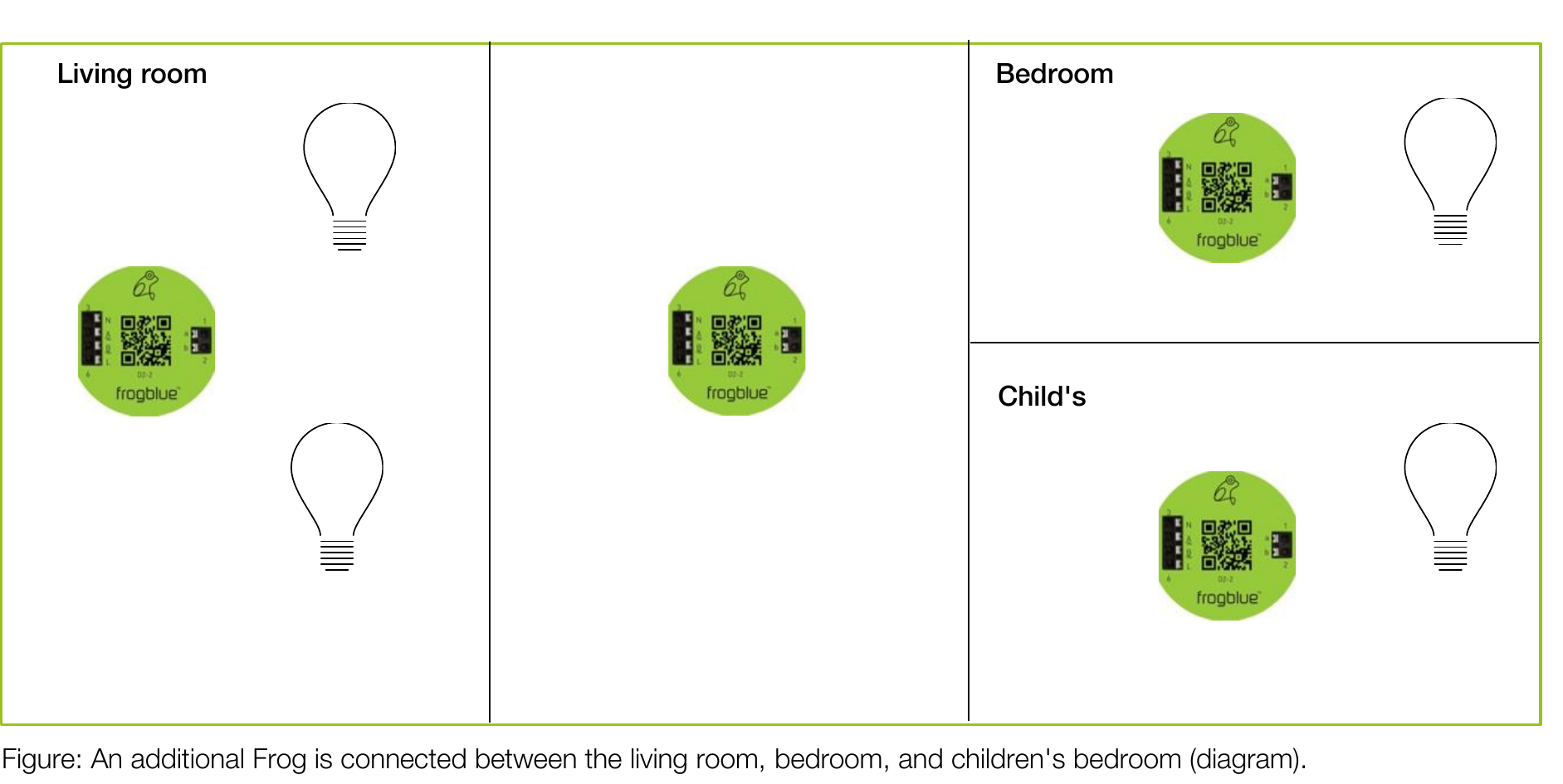
Figure: An additional Frog is connected between the living room, bedroom, and children’s bedroom (diagram).
A Frog which is used as repeater may only be connected to the power in the flush-mounted box and added to the project via the frogProject app. The inputs and outputs do not have to be configured. Any Frog can be used as a repeater.
Note Messages are automatically forwarded or redirected.
7 Installing and updating the frogProject app
You can install and use the frogProject app on the operating systems iOS, Android and Windows (full version).
You can download the frogProject app from the Google Play Store and the Apple App Store.
You can download the Windows version of frogProject from the frogblue website. → frogblue.com.
Note The Android and iOS versions of the frogProject app run exclusively on tablets. The Android and iOS versions of the frogProject app can be found in the Google Play Store and in the Apple App Store via tablet only.
Note If a new version of the frogware is available, the latest version of the frogware is automatically downloaded along with the frogblue Project app. Android: Is stored in the internal memory in the Documents folder. iOS: Is stored in the internal memory. Windows: Is stored in the /User/Username/Documents/frogblue folder. For information on updating the frogware of Frogs and frogKeys, see → Updating frogware, page 155.
 Search the Google Play Store for frogProject.
Figure: frogProject app in the Google Play Store.
In the Google Play Store, tap Install to install the frogProject app.
 Search the Apple App Store for frogProject.
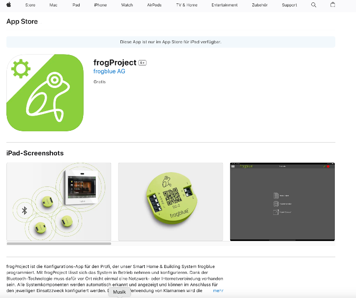
Figure: frogProject app in the Apple App Store.
In the Apple App Store, tap Install to install the frogProject app.
7.1 Starting frogProject
Note Make sure Bluetooth® (version 4.2 or higher) is enabled on your tablet. Android: Settings -> Connections -> Bluetooth iOS: Settings -> Bluetooth
To start the frogProject app, tap the following button on your tablet after the installation: frogProject 
When starting the frogProject app, allow access to the location of the device. This is required by Bluetooth®.
Allow access to the photos, media, and files so that configuration files can be saved.
Assign a name to the tablet. This can be used to determine on which tablet a configuration was created.
The start screen is displayed.

Figure: Start screen of the frogProject app.
7.2 Installing the frogProject app in Windows
The frogProject app can be used on Windows 7/8/10 64bit. A USB2.0 interface and a frogLink are required. For information on frogLinks, see → Configuring frogLinks, page 141.
- Download the frogProject app from the frogblue website → frogblue.com
- Unzip the zip file.
- Double-click the unzipped .exe file.
- Follow the installation instructions on the screen.
During installation, a dialog box for installing device software is displayed.
 Figure: Dialog box for installing the device software.
 - Click Install. The frogProject app is installed. During installation, the frogware is stored in the folder User/Username/Documents/frogblue. To be able to use the frogProject app in Windows, you need a frogLink for which editing mode frogblue mode is configured. A frogLink is a Bluetooth® LE USB stick for the configuration and control of the frogblue components with Windows computers. For information on how to configure a frogLink, see section → Configuring frogLinks, page 141.
7.3 Updating the frogProject app
New versions of the frogProject app are available for download in the Google Play Store or Apple App Store.
A new version of the frogware can also be made available with a new version of the frogProject app. When the frogProject app is downloaded, the frogware is automatically downloaded along with it.
Depending on the settings in the Google Play Store the frogProject app will be updated automatically.
How to check on an Android device whether apps are updated automatically:
- Open the Play Store app.
- Tap the Menu icon, then tap Settings.
- Tap Automatic app updates.
- Check the option Do not update app automatically.
Depending on the settings in the Apple App Store, the frogProject app will be updated automatically.
How to check on an iOS device whether apps are updated automatically:
- Open the Apple App Store.
- Tap App Store and then Preferences.
- Check the Automatic Updates option.
8 frogProject – Overview of icons and color codes
This chapter provides an overview of the functions of the icons and the color codes used for the configuration screen.
The devices of the frogblue system are configured in the configuration screen.
The configuration screen is divided into the following areas:
- Title bar: Here the menu is available and access to various configuration options is provided.
- Device list: Here all devices such as Frogs, frogKeys, or frogDisplay that have been added to the project are listed.
- Display area: Here an overview is provided of a selected device. In the display area the configuration of the device can be saved, and switches can be configured.
- Configuration area: Here the inputs and outputs of the device can be configured.
- Footer: Further options are available here for the individual areas.
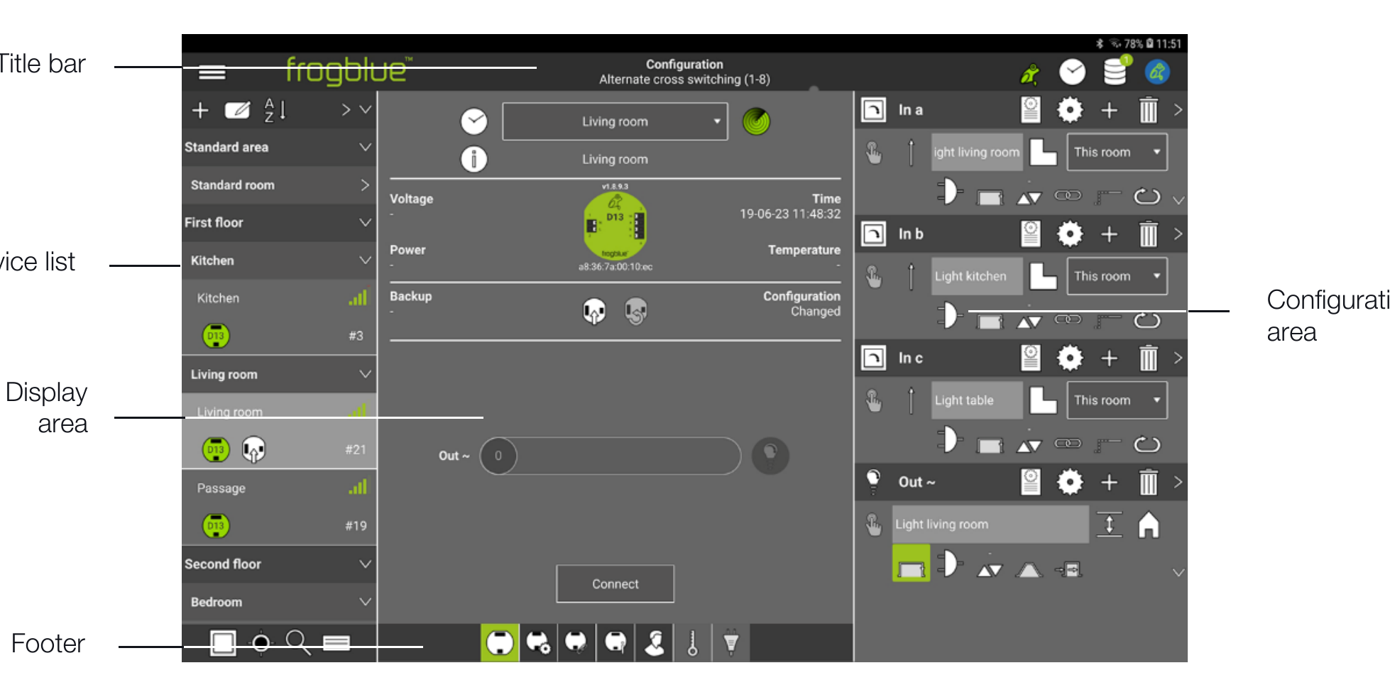
Figure: Configuration screen.
In the following sections, the icons are introduced along with the colors and color codes for the individual areas.
8.1 Title bar
 |
Menu | Access to all functions. | |
 |
Backup status | Display the current backup status. | |
 |
Time server configuration | Configuration of the Time Frog. | |
 |
Creating a backup | Save the configuration in a Frog or file. | → page 155 |
 |
Integrated Bluetooth | If a frogDisplay is available in the project, an IP connection to the frogDisplay can be established here. |
Colors and color codes in the title bar
|
Time server configuration | white | Status OK. |
| red flashing | At least one Frog has the wrong time. | ||
| blue flashing | The Time Frog just sent a message. | ||
| white flashing | An error has occurred. | ||
|
Backup status | red | No project backup was saved, or the configuration of a Frog was changed, and no project backup was saved in the frogs. |
| green | The project backup matches the configuration of the Frogs. The system is up to date. | ||
| with crown | Project password and device key match the last project backup. | ||
| without crown | Project password and device key do not match the last project backup. |
8.2 Device list
 |
Search for inputs | Displays the nearest Frog where an input signal is registered. | |
 |
Show room | Displays the room of the currently selected Frog. | |
 |
Search for Frogs/rooms | Search for Frogs or rooms using a keyword. | |
 |
Display details | Displays the detailed information of the devices in the device list. | |
 |
Add | Add Frogs, rooms, and areas to a project. | → page 60 |
 |
Edit | Edit mode for adding rooms. | → page 66 |
 |
Sort devices | Sorting of devices according to different criteria. | |
 |
Select Frog | Selection of a Frog to display the details in the display area and configuration area. | → page 65 |
Colors and color codes in the device list
|
Frogs | green | Standard |
| Frog with clock symbol | Time Frog | ||
| blue | Master | ||
| white | Clone | ||
| orange | Clone with old configuration. | ||
 |
Signal strength | green | Within direct range the tablet. |
| orange | In mesh range. | ||
| red | Unavailable. | ||
| blue | Connected. | ||
| white | Connection is being established. |
8.3 Display area
 |
Time Frog | Frog with clock (displayed on the bottom right of the Frog.) | |
 |
Room detection | Activating room detection. | → page 126 |
 |
Device note | Here you can add a note text for the device. | |
 |
Save configuration | Load configuration onto Frog. | → page 127 |
 |
Undo changes | Undo the changes since the last save. | → page 127 |
 |
Load configuration | Loads the configuration of the frogDisplay into the frogProject App. | |
| Connection | Establishing a fast Bluetooth® connection to a Frog. | → page 198 | |
 |
Frog view | View of the configuration of a Frog (standard view). | → page Fehler! Textmarke nicht definiert. |
 |
Advanced device settings | Definition of power limits for outputs, input debounce time, dim curves and lamp failure detection. | → page Fehler! Textmarke nicht definiert. |
 |
Master/clone configuration | Configuration of master and clone frogs. | → page 122 |
 |
Status | Display of how inputs and outputs are assigned | → page 125 |
 |
User view | View to add buttons and switches to a Frog. | → page 78 |
 |
Monitor temperature | Monitoring the temperature in housing of the Frog. | → page 126 |
 |
Power measurement | Measuring power consumption at the outputs. | → page 126 |
8.4 Configuration area
In the configuration area you can configure the inputs and outputs.
8.4.1 Inputs
| In a, In b,… | Name of the input | → page 70 | |
 |
Macro | Assigning a macro to an input. | → page 174 |
 |
System group | Assigning a system group to an input. | → page 185 |
 |
Function | A selection of the following functions for an input: | → page 71 |
Light
 |
Button - light | A button. |
 |
Button - dim | A button for a dimmable lamp. |
 |
Button - dim to warm | A button for a dimmable heat lamp. |
 |
Button - color shift | A button for controlling the color. |
 |
Button - tunable white shift | A button to control the light intensity and color. |
 |
Button - custom | A button that can be configured individually. |
 |
Button - on | A button for a lamp which switches on at click. |
 |
Button - off | A button for a lamp which switches off at click. |
RGBW presets
 |
2-buttons control – brightness | A button for controlling the hue of a light device. |
 |
2-buttons control - color | A button for controlling the saturation of a light device. |
 |
1-button control | A button on with a function key for control. |
 |
1-button control - tunable white | A button for controlling the color temperature of a light device. |
Motor
 |
Button - shutter | A button for a roller shutter to go up and down. |
 |
Button - screen | A button for a screen to go up and down. |
|
Button - skylight | A button to open and close a skylight. |
|
Button - awning | A button for an awning to go up and down. |
 |
Button – custom motor | A button for a user defined motor. |
Door
 |
Button - bell | A button for a bell. |
 |
Button - door | A button for opening a door. |
 |
Button – furniture lock | A button to open a furniture lock. |
Ventilation
 |
Button - ventilation | A button to regulate a ventilation. |
|
Button – adjustable ventilation | A button to regulate an adjustable ventilation. |
Status
Predefined statuses: Status, Status night, Status alarm, Status frost, Status wind, Status smoke, Status rain, Status fire, Status gas, Status flow, Status level, Status leak, Status window tilted, Status window open, Status window closed, Status door open, Status door closes, Status door locked, Status furniture door open, Status furniture door closed, Status furniture door locked, Status garage open, Status garage closed, Status garage locked, Status gate open, Status gate closed, Status gate locked.
Other
 |
Switch | Ein einfacher Schalter. |
 |
Motion | Möglichkeit, um einen Bewegungsmelder abzufragen. |
 |
Custom | Möglichkeit, um einen eigenen Taster zu definieren. |
 |
Scene | Möglichkeit, einen Schalter in eine Szene zu integrieren. |
Function macro
 |
Save | → page 175 |
Action
| — | Action | A selection of the following actions for an input: | → page 72 |
 |
Inactive | The input is not assigned. | |
 |
Status | A status message is sent whenever there is a change in status. If there is no change, the status is repeated cyclically. | |
 |
Rising | Short input signal in the case of a ascending edge. A change of 0 to 1. | |
 |
Falling | Short input signal in the case of an ascending edge. A change of 1 to 0. | |
 |
Edge | Short input signal in the case of an ascending and falling edge. | |
 |
Click | A short input signal < 250 ms (the value can be changed in the settings). | |
 |
Double click | Two input signals in short succession. | |
 |
Triple click | Three input signals in short succession. | |
 |
Hold | Levels 0 and 1 are available. The signal is triggered when for longer than 250 ms (default) level 1 is present, that is, the switch is closed. A level hold time increases this 250 ms by the hold time. | |
 |
Release | The signal is triggered when the level (set hold time) has elapsed, and the button is released (long hold time). | |
 |
Click hold | The signal is triggered if, after a click, the signal is present for longer than 250 ms or if the button is held down again after a click. | |
 |
Click release | The signal is triggered when the button is held again after a click and then released. | |
 |
Double click hold | The signal is triggered if the signal is present for longer than 250ms after a double click, or if the button is held down again after a double click. | |
 |
Double click release | The signal is triggered when the button is held again after a double click and then released. |
Enter signal
| Enter signal | Entry field to define messages. | → page 71 | |
|
Add messages | Add further messages to an input. | → page 80 |
 |
Send message | Send message immediately. | → page 71 |
 |
Range | Range of the message in the frogblue system. | → page 117 |
 |
Gate/Time editor | Gate/Time editor to define logic functions. | → page 103 |
 |
Minimal on | Minimal on time. Time adjustable from 1/10s to 63h. | → page 106 |
 |
Dim | Values for dimming: up/down activate/deactivate; brightness pre-settings; dimming speed. | → page 106 |
 |
Input matrix | Logical linking of inputs. | → page 107 |
 |
Hold time | Dead time for Hold and Release actions. | → page 108 |
 |
Rolling messages | Sending the next message with the same action. | → page 108 |
 |
Shutter | Setting the shading position and slat position for roller shutters. | → page 112 |
 |
Status | Definition of a status. | → page 109 |
8.4.2 Outputs
| Out A, Out B | Name of the output. | → page 73 | |
 |
Macro | Assigning a macro to an output. | → page 174 |
 |
System group | Assigning a system group to an output. | → page 185 |
 |
Function | A selection of the following connections for an output: | → page 74 |
Light
 |
Light | A switchable light. |
 |
Dimmable light | A dimmable light. |
 |
Status light | Shows the state for a status (does not respond to TYPE:Light). |
Door
 |
Bell | A simple doorbell. |
 |
Door | Connection for a door. |
 |
Gate | Connection for a gate. |
 |
Garage | Connection for a garage. |
 |
Furniture lock | Connection for a furniture lock. |
Ventilation
|
Ventilation | Connection for a ventilation. |
|
Adjustable ventilation | Connection for an adjustable ventilation. |
Other
 |
Irrigation | Connection for an irrigation. |
 |
Pump | Connection for a pump. |
 |
Heating | Connection for a heating. |
 |
Climate | Connection for a cooling system. |
 |
Custom | Possibility to define your own connection. |
Function macro
|
Save | → page 175 |
Action
| — | Action | A selection of the following actions for an output: | → page 75 |
 |
Toggle | Switch on and off. | |
 |
Switch in | Switch on only. | |
 |
Switch off | Switch off only. | |
 |
Follow | Follow the status of another output, → page 116. | |
 |
Dim | Dimming from minimum 20% to maximum 100% (default). | |
 |
Dim up | Dimmer increase only. | |
 |
Dim down | Dimmer decrease only. | |
 |
Time | The output is switched at the set time. | |
 |
On | Without gate: The output is on at the set brightness level. With gate: The output is on when the gate is TRUE. If the gate is FALSE, the output goes off. | |
 |
Off | Without gate: The output is off at the set brightness value. With gate: The output is off if the gate is TRUE. If the gate is FALSE, the output goes off. | |
 |
On transparency | Without gate: The output is on at the set brightness level. With gate: The output is on when the gate is TRUE. If the gate is FALSE, the output is assigned the state by the incoming messages. | |
 |
Off transparency | Without gate: The output is off at the set brightness value. With gate: The output is off if the gate is TRUE. If the gate is FALSE, the output is assigned the state by the incoming messages. |
Enter signal
| Enter signal | Entry field to define messages. | → page 74 | |
|
Add messages | Add further messages to an output. | → page 80 |
 |
Other messages | Displays additional entries for a message. | → page 80 |
 |
Detailed view | Displays all configurations of a message. | → page 74 |
 |
Delete message | Delete message and its configuration | |
|
Send message | Send message immediately. | → page 74 |
|
Range | Range of the message in the frogblue system. | → page 117 |
|
Time control | Time when the output connected to the input is to be switched off. | → page 106 |
 |
Gate/Time editor | Gate/Time editor to define logic functions | → page 103 |
|
Dim | Values for dimming. | → page 106 |
 |
Soft Function | Duration of dimming. | → page 111 |
 |
Delay function | Time to wait for a message until the output is switched off. | → page 111 |
|
Shutter | Setting the travel time and reversal time for roller shutters. | → page 112 |