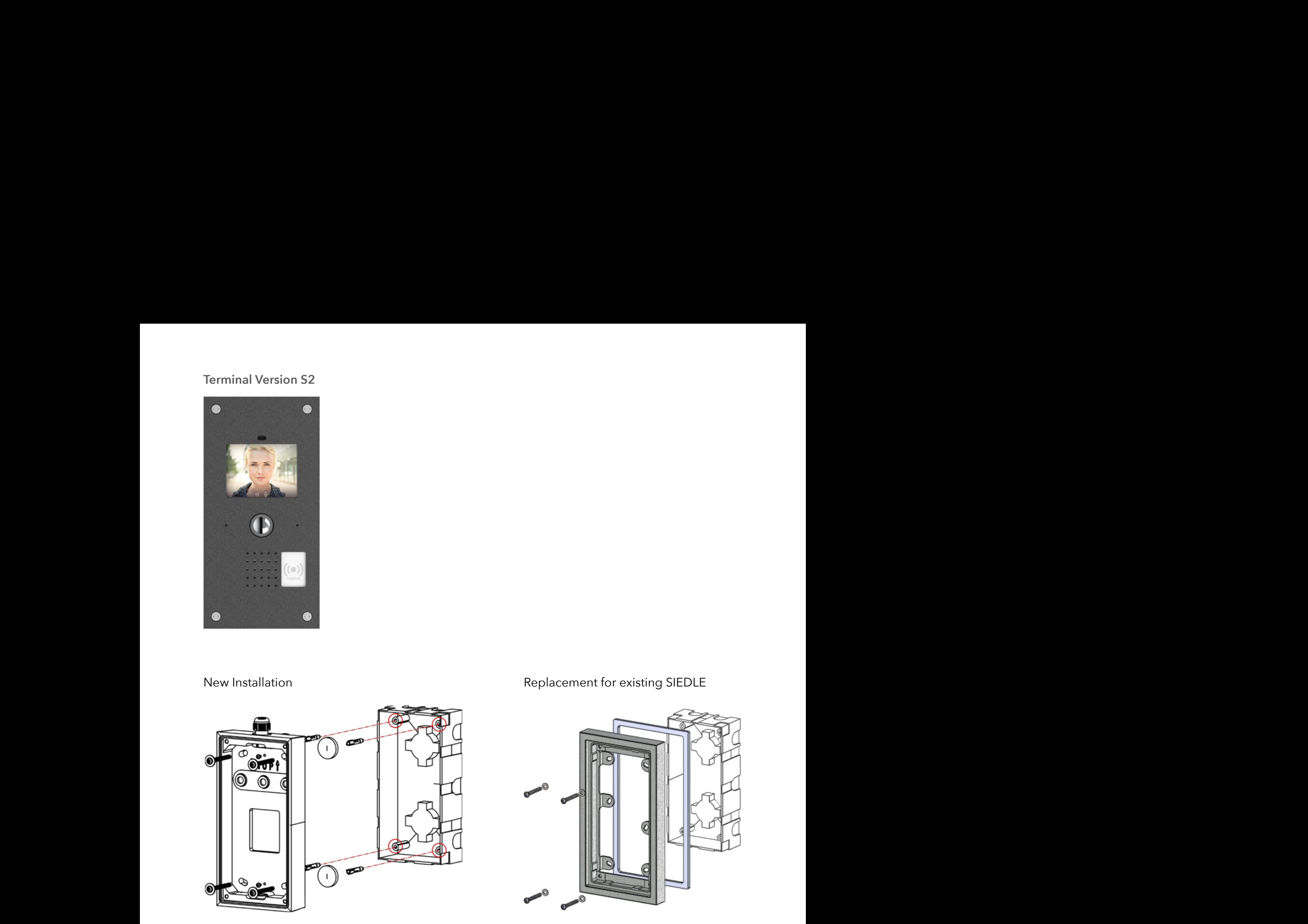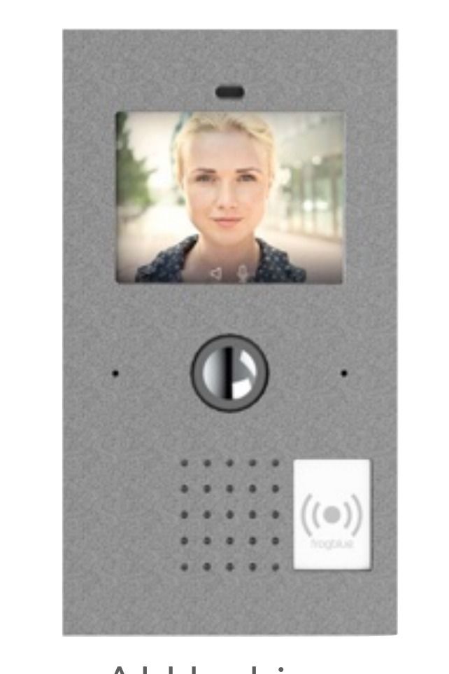

The frogTerminal is a SIP video intercom with multi-factor authentication, decentralised RFID access control, and Bluetooth/IP automation. It supports direct SIP calls, multi-server registration, real-time security alerts, and third-party VMS/SIP integration.
A. Introduction, System Overview, and Key Features
1. Overview
The frogTerminal offers functionality that goes far beyond a traditional video intercom system. Its key feature is its network connection and direct utilisation of the global IP telephony standard SIP, without requiring an additional box. This enables all SIP-compliant devices to be called directly without a server or cloud.
In commercial multi-tenant scenarios, tenants often have their own IP telephony systems with integrated SIP servers. In such cases, intercom systems typically connect to these systems via external calls. The frogTerminal, however, can register simultaneously as an extension with multiple SIP servers, optimising the use of telephony system features.
The integrated 8-megapixel camera with hemispheric optics provide for a 180° panoramic view, all actions at the terminal can trigger a recording. It also integrates with video management software like MxMC® and supports real-time, full HD video streaming via RTSP/H.264.
Connection options for the frogTerminal include:
-
1-Gbit Ethernet with Power over Ethernet (PoE) via the network cable.
-
12-24VDC (12W) (reverse-polarity protected)
-
24VAC (12W)
-
For simple applications, the integrated relay can directly handle door unlocking, 2 input ports enable direct connection to external doorbell buttons or magnetic door contacts.
The integrated touch display allows for the virtual design of doorbell labels. Alternatively, a party can be discreetly dialled using an apartment number. General PIN codes can also be entered for door unlocking or special functions.
A smartphone call is initiated as a standard phone call when the doorbell rings. This requires registration in frogblue’s cloud (with SIP server) and the installation of the frogSIP app on the smartphone.
The integrated RFID reader facilitates access control and time tracking. By combining RFID with a PIN entered via the display, the system enables two-factor authentication. Access control can be further restricted using customised weekly schedules. For enhanced security, three-factor authentication can also be enabled, incorporating an automatic phone call as an additional layer of verification. This three-factor authentication can be configured to activate based on a timetable, such as after hours, ensuring stricter access control during high-risk periods.
The frogTerminal supports multi-party and multi-tenant capabilities, as each party can individually configure its access parameters. Third-party hardware, such as barrier systems or KNX-based lighting controls, can be integrated via IP commands. Frogblue building control components are directly connected via Bluetooth, allowing simple deployment of frogblue modules for functions like gate control or door unlocking. DALI lights are supported directly with our DALI frog. For a detailed overview of integration options, refer to the frogblue API documentation and our competitor analysis.
The commissioning process is guided by a user-friendly wizard, which walks the administrator through the necessary steps to configure the terminal.
2. Key Advantages of the frogTerminal
-
Integrated 8 MP Camera – Provides visual verification and 180° panoramic recordings
-
Built-in Video-SIP Telephony – Enables remote operation by reception or security staff
-
Advanced Multi-Factor Authentication – Supports multi-factor authentication, including RFID, PIN, video verification call, and advanced integrations
-
Global Video Calls – Directly connects to smartphones or SIP phones worldwide
-
Real-Time Security Alerts – Sends call notifications for unauthorised access attempts or restricted user access
-
Flexible Multi-Terminal Access Management – Supports up to 9 access zones, even without an IP connection
-
Optional User Group Management – Centralised storage in the frogCloud (in development)
-
Seamless Hardware Integration – Supports IP or Bluetooth-based devices for light control, gate opening, and more
-
Standalone Operation – No additional hardware or external computer systems required
-
High-Speed Connectivity – 1-Gbit network connection with PoE Class 3 or Wi-Fi support (also compatible with 24V AC/12V DC power)
-
Energy-Efficient Design – Power consumption ranges from 5 to 8 watts
-
3. Telephony Overview
3.1. Worldwide Telephony Standard
The frogTerminal utilises the international telephony standard SIP for video and audio communication. This makes all SIP-compliant endpoints accessible directly, without additional hardware. Nearly all modern telephone systems are based on this standard, facilitating the easy integration of third-party devices.
Typically, all devices register with a SIP server that handles call routing. This SIP server can be installed locally or made available over the internet for worldwide telephony.
The frogTerminal is designed to support local telephony without relying on an internet connection, enabling on-site communication with no cloud required. For connecting multiple company locations, a virtual private network (VPN) offers a secure private solution. Only when integrating independent locations or smartphones without VPN into the system, an internet- based cloud-service with SIP server becomes essential. To make this easy, frogblue provides our own SIP cloud with automated configuration options, hosted in a secure German data centre.
3.2. Direct Integration of End-point Devices
IP telephones, such as those from Grandstream®, can be called directly by the frogTerminal without additional components. A SIP server is not required as the Direct SIP Call functionality is used, provided the device is reachable via an IP address.
For small setups, the simplest configuration consists of a frogTerminal and a SIP desktop phone. This eliminates the need for SIP server hardware and management.
3.3. The frogDisplay
With a simple software update, the existing frogDisplay can be upgraded to function as an indoor station. It connects via Wi-Fi and operates on 100-240V power. The updated software enables automatic configuration with the frogTerminal, and a simple toggle switch allows it to function as a doorbell.
Currently, devices are added manually to the bell buttons via their IP address. An upcoming software update will introduce automatic configuration.
The frogTerminal offers 4 modes for auto-configuring Displays (currently in development):
Bell Mode: All discovered Displays are automatically grouped under a standard doorbell label in a cyclical process.
Room Mode: The Display’s assigned room name (e.g., "Foyer") is used as the doorbell label. If multiple Displays share the same room name, they are grouped under a single bell button.
Name Mode: Displays can be registered with a custom name (e.g., "Tom Smith" or "Reception"), which is automatically assigned as the doorbell label. Displays with the same name are grouped together under one label.
Terminal Mode: The name entered in the Terminal is used as the doorbell label. If no name is configured, the system defaults to the Display’s name, and if that is unavailable, it falls back to the room name.
3.4. The frogStation
The frogStation is a frogblue device that serves as the primary remote station for the frogTerminal. Installed, for example, in an apartment, it provides a user interface for interacting with the frogTerminal at the entrance. It is similar in design to the frogTerminal, but without a camera module. Unlike the frogDisplay it features enhanced audio capabilities for superior sound quality and supports both Wi-Fi and wired network connectivity with PoE for increased reliability.
It features 2 switching inputs and a 24V/1A relay for external controls, enabling seamless integration with additional systems.
Thanks to its enhanced mechanical and acoustic design, the frogStation delivers superior and louder sound quality compared to the frogDisplay.
3.5. Integration with Telephony Systems
IP telephony systems typically feature a PBX with integrated SIP server for registering devices and routing calls. The frogTerminal can register with such SIP servers, functioning as an extension of existing telephone systems.
In multi-tenant environments, tenants often rely on separate telephone systems. The solution: the frogTerminal supports simultaneous registration and operates with multiple SIP servers at the same time, seamlessly integrating across multiple telephony systems.
3.6. frogSIP App and Calling a Smartphone
Smartphone calls require push notifications from the device manufacturer to wake the phone and launch the telephony app. To facilitate this, frogblue operates a dedicated telephony cloud including SIP server, ensuring reliable delivery of the required push notifications.
The smartphone must have the frogSIP App installed, which receives calls in the same familiar way as regular phone calls. This setup is free to use and, apart from email verification, remains anonymous.
frogSIP is engineered for seamless integration with frogTerminal and offers a host of advanced features:
Seamless Device Pairing: Easily connect and pair devices for a smooth setup experience.
Integrated Automation: Fully integrated into the frogblue automation system, frogSIP streamlines centralised management.
Direct Access & Log Control: Gain immediate control over access permissions, call logs, recordings, and playback.
Multi-Door Support: Manage multiple doors effortlessly, enhancing both security and convenience.
To connect personal devices via the internet, frogCloud is essential. The frogTerminal automatically registers with the cloud when configured by the Installer or System Administrator.
3.7. Mixed Operation
The frogTerminal supports simultaneous operation of all modes:
Direct SIP calls to local devices
Registration with multiple telephony systems (using various SIP servers)
Smartphone calls via the frogCloud
3.8. Video Intercom
With an integrated camera, audio, and display, the frogTerminal offers comprehensive video intercom capabilities. In contrast, the frogStation and frogDisplay support video reception but are optimised for audio-only transmission. New features such as announcements and baby monitor functions are currently under development.
4. Access Control Overview
4.1. Introduction
The frogTerminal offers convenient, time-controlled and multi-factor access control using PIN Codes, RFID cards, and Phone Calls. A cloud or network connection is not required for these functions.
The terminal supports the Mifare DESFire EV2 international card standard. RFID cards or key tags only need to be configured on one frogTerminal, and they can be used across all terminals in the same project with no additional setup. A network connection is not required, though it simplifies administration for remote management.
4.2. Decentralised Access Control
With frogblue, user data is stored directly on RFID cards or key tags. Terminals read the data during card scans, eliminating the need for network or cloud connections.
For all terminals in a project to read the encrypted data, they must share the same encryption settings, which include:
A 10-digit RFID code
Project Timestamp
Changes to user data—such as updated PINs or access permissions—only need to be made on one terminal (for example, at the main entrance). The system then automatically updates the card with the new data the next time it is used, ensuring a seamless update process. Blocking a card follows the same process.
Note: Synchronisation via IP network and locally via Bluetooth + a cloud-based access management system with time tracking is currently in development.
4.3. NFC/RFID Card Information
The RFID card stores all essential user access data, including:
Name, first name, and personnel number
Issue date
Validity period (start date/time to end date/time)
Personal PIN code for access
Weekly access schedules
Up to 9 access zones
Each frogTerminal reads and interprets the card’s contents whenever it is scanned. For example, changes to PINs or access schedules are automatically updated upon reading the card.
The terminal logs the card content, including timestamps for each operation. User information and access times can be viewed directly on the terminal display or via the frogSIP App. If a network connection is available, these logs can be reviewed remotely via a web browser.
4.4. Access Functions
RFID cards or key tags define user-specific access rules. These include PINs, weekly schedules, and access zones. Additional terminal-specific settings can override or adjust these rules (Access Control→Terminal Settings):
PIN Requirements
Certain doors can be configured to allow access without requiring the user’s personal PIN code e.g. for internal doors. (PIN code Source: "NONE")
Alternatively, a door can be secured with a terminal-specific code. This PIN applies to all users equally, overriding personal PINs. (PIN code Source: "TERMINAL")
Time Restrictions
Access times can be based on the individual card schedule or configured globally for all users at the terminal (Time Table Source: “Card” or "TERMINAL").
Time restrictions can also be disabled entirely for specific terminals (Time Table Source: "NONE").
4.5. Special Access Functions
RFID cards can store additional features:
Automatic SIP Phone Call (SIP URI)
A phone number which can be dialled automatically when the card is presented.
IP Link - automatically trigger or integrate external systems (e.g., time tracking or special functions).
These features allow RFID cards to act as function triggers rather than just user-specific access tools. For instance, an RFID card labeled "Storage Access" could be shared as needed.
Special Function Settings at Terminals have 3 general options:
NONE: Special functionality is disabled.
CARD: The function stored on the RFID card is activated.
Terminal: The function stored on the Terminal is activated in place of that on the Card.
4.6. frogTerminal Access Control Settings Overview
The settings of the terminal can be configured via the on-screen display and remotely through the web interface. The following key access parameters must be set during initialisation:
RFID Code: 10-digit encryption code for cards (hashed for security)
Project Date: Shared date for card encryption across all devices in the project
Project Number: Shared ID for project identification across all devices in the project (1-32,767)
Zone: Assign the terminal to one of 9 access zones
PIN Code Source: None, Card, Terminal
Terminal PIN Code: 6-digit Access Code
Time Table Source: None, Card, Terminal
Terminal Table: Time Table for Access at this Terminal only
Time Table Exception: None, PIN, or Request e.g. for access outside regular schedules
Authentication Call: Never, Card, On Exception, Always
URL Source: None, Card, Terminal - The source for the Web-hook URL
Terminal URL: Web-hook URL to for realtime integration of access events
Date of Issue: Minimum Issue Date - Cards issued before this date are invalid
For different levels of security at various terminals, the following settings can be applied:
NONE: Function is not required, e.g., access without PIN verification at specific Terminal.
CARD: The function parameter is read from the RFID card.
STATION: The parameter is retrieved from the terminal itself - e.g., a global PIN for all users at a specific location or direct integration at this specific access point i.e. time and attendance, worksite management, nurse call, or logistics systems.
PIN Authentication: Access can occur without an RFID card, using only a PIN stored in the terminal.
4.7. Adding and Blocking RFID Cards
Adding Cards:
A user can self-register an RFID card if an authorised station confirms the action via a SIP phone call. The user enters their personal details (e.g., name, personnel number), while an administrator approves the data and sets additional parameters.
Blocking Cards:
Blocking a card must be performed locally on all terminals, as each maintains its own negative list of blocked cards. Remote blocking via the web interface is possible.
Note: In a cloud-based solution, blocking is centralised and does not require action at each terminal.
4.8. User Display at the Terminal
The terminal displays the following for users:
Large bell icon: For unauthenticated users
Keypad menu: For PIN entry
Settings menu: For admin access
Date and time display: Helps identify incorrect terminal settings
Time tracking options: "Check-in," "Break," and "Check-out" menus for time tracking
Note: As an example the ODOO ERP system includes a time tracking module, an integrated solution with frogblue and ODOO is currently in development.
5. Hardware Integrations
5.1. Relays and Inputs
The frogSIP terminal includes a potential-free relay output (24V/1A), which can directly control a door lock when connected to an external power supply (12V or 24V).
It also features 2 input ports that can be directly connected to buttons or magnetic contacts without requiring additional power supply. These inputs can be configured for:
Triggering a doorbell via an external button to call a SIP endpoint
Automatic calls triggered by sensors (e.g., motion detectors or light barriers)
Sending signals via Bluetooth Mesh (e.g., for lighting control) or IP
Monitoring door status with magnetic contacts (open/closed); with the second input, it can register whether the door is locked
5.2. IP Link Integration
The terminal supports activating external systems via IP links. For example, scanning an RFID card or pressing a button can trigger functions such as:
Opening a parking barrier
Raising a roller door
Triggering video recordings on an external camera
5.3. PIN-Control
Preconfigured Function PIN codes linked to specific IP commands or Mesh messages can be used to control external systems or hardware. Function PINs can be shared among all users and used to control for example: lighting or gates, security cameras, or third-party software.
5.4. USB-C Expansion (USB 2.0 compatible)
The terminal’s USB-C port enables connections for frogblue hardware expansions, including:
Internal hardware (e.g., sensors, mechanical keypads)
External USB devices (e.g., local data storage or additional control modules)
5.5. Bluetooth Mesh Integration
The terminal includes a frogblue Bluetooth Mesh interface for integration into frogblue projects. It fully integrates into frogblue projects via the ProjectApp.
5.6. Vario Module Slot
The frogSIP Terminal Vario includes a dedicated slot for a Vario module, enabling the integration of third-party modules such as:
Time tracking systems
Fingerprint readers
At this stage, integration is supported only for the Siedle 1 and 2 range via direct switching inputs/outputs.
These modules can function independently or be linked to the terminal’s hardware to trigger predefined actions.
6. Core Features
6.1. Access Control Features
The frogTerminal supports multi-party doorbell functionality, enabling calls to SIP endpoints or smartphones for access control. Two-way video and audio communication is possible with hands-free operation. Access functions include:
Doorbell and manual door unlocking: Calls to smartphones or SIP phones with rerouting outside access times.
PIN-controlled access: Shared or user-specific PINs with individual schedules.
RFID cards or tags (DESFire EV2 standard): Weekly schedules supported.
Two-factor authentication: RFID card + personal PIN with schedules.
Three-factor authentication: RFID card + PIN + visual verification via phone call.
Visual verification via phone call: Outside regular access times.
frogKey (Bluetooth Transponder): For vehicle-based access with time restrictions.
6.2. SIP Telephony Features
The frogSIP terminal features a globally standardised SIP telephony module with two-way video support over the network. Key benefits include:
Direct compatibility with SIP endpoints (e.g., Grandstream IP video phones)
High video and audio quality without external conversion modules, avoiding quality loss
Direct IP calling without a SIP server for simpler setups
Multi-SIP server support for complex installations
Smartphone integration via the frogSIP app and frogblue SIP server, hosted in a secure German data centre
The frogSIP app offers direct integration of frogblue functions such as:
Door unlocking
Light control
Camera adjustments
Recording access and playback
Third-party SIP apps like LinPhone, 3CX, Bria, etc. can also be used but may require DTMF key- based operation for additional functions.
6.3. Recording and Event Management Features
The terminal can trigger recordings for every action. Features include:
Full-resolution raw image storage (4 MB) for post-processing and zooming
Configurable pre- and post-alarm snapshots
Detailed metadata for every recording, including:
RFID card information
Video feed parameters (e.g., exposure settings)
6.4. SIP Telephony Registration and Costs
Registration of smartphones is quick and easy using a QR code generated by the terminal. This automatically configures the doorbell to route calls to the smartphone.
A single smartphone registration per terminal is free and anonymous, requiring only email confirmation within 12 hours. Advanced features like external cloud storage or additional frogblue SIP users are billed monthly.
7. Access Management
7.1. Cloud-Based Access Management (frogAccessControl)
For large networks with multiple terminals at different locations, centralised administration via the cloud-based frogAccessControl is the optimal solution. This system enables:
Instant updates to all terminals with a single action
Immediate blocking of RFID cards across all terminals
This cloud solution is currently in development and builds upon the functionality of frogControl and the frogSIP server, integrating a database for centralised management.
7.2. Local User Management (frogEasyAccess)
For smaller setups without intensive administration, the frogEasyAccess solution offers simple and efficient user management without requiring cloud integration. This approach:
Allows RFID cards configured at one terminal to work seamlessly on others within the same project, without additional setup.
Stores user data directly on RFID cards, including:
PIN code
Weekly schedules
Zone authorisations
All terminals within a project must share the same RFID encryption settings (RFID code and project date) for compatibility.
Key Benefits:
Cards initialised at one terminal are automatically functional on others within the same project.
Terminals can be grouped into up to 9 access zones, with cards able to be assigned to multiple zones.
Security settings can be adjusted for each terminal (e.g., disabling PIN requirements at some terminals).
Multi-factor authentication can be enabled for additional security, e.g. requiring video verification via SIP phone call.
Note: An IP network or Bluetooth Mesh is recommended to ensure time and date synchronisation across terminals.
7.3. RFID Card Encryption
RFID cards are encrypted for security. Terminals in a project must use the same encryption settings, which are derived from:
A 10-digit Master Key
The project’s issue date
The project’s identifier (1-32,767)
This combination generates a unique key through a hash algorithm. Multiple projects can coexist without conflicts, as the project date & identifier ensures uniqueness even if the Master Key is accidentally reused.
7.4. RFID Card Initialisation and Authentication
When initialised at a terminal, RFID cards store:
User details (name, personnel number)
Access information (PIN, zones, weekly schedules)
Terminals read the card data for local, decentralised access decisions, even without a network connection. This eliminates the need for manual registration at every terminal.
Remote management of user data is also possible through:
The terminal’s web interface
The frogSIP app on a smartphone
This provides the foundation for enhanced cloud functionality.
7.5. Information Stored on the Card
RFID cards contain the following information:
User details: Name, first name, personnel number
Validity period: Start and end dates
Zone assignments (up to 9 zones)
A 6-digit personal PIN
Weekly access schedules
IP link for triggering functions over the network
SIP phone number for automatic calls upon card scanning
Terminal ID and issue date of the initialising terminal
An AllStation flag allowing the card to work on all terminals within the project
Customisation per terminal: Specific parameters (e.g., PIN requirements or access schedules) can be adjusted at individual terminals without modifying the card.
7.6. Terminal Settings
| Step | Description |
|---|---|
| 1 | In the right-hand panel, your frogTerminals are displayed. After clicking on the device name, the selection menu opens. The selection menu is divided into three sections: Under Device Information, you will find information about the Terminal. RFID and PIN Settings provide quick access for managing cards and function PINs. The last two entries provide quick access for opening the door and executing function PINs. |
Configuration data for Terminals includes:
RFID Code: Encryption code shared across the project.
Project Date: Used with the RFID code to generate encryption keys.
Authentication Modes: PIN, CARD, TERMINAL, PIN request, CARD request.
Zone Assignment: One of 9 zones for the terminal.
PIN Source: NONE, CARD, or TERMINAL.
Access Time Source: NONE, CARD, or TERMINAL.
Exception Handling: NONE, PIN, CLOUD, or REQUEST (e.g., for emergency access).
Issue Date: Only cards issued after this date are valid.
7.7. Adding and Blocking Cards
Users can add RFID cards themselves with approval via a SIP phone call from an authorised station.
Adding RFID Cards:
Admin add locally.
Admin over third party RFID reader (future / typical hotel solution / Web/Cloud).
In development - frogCast Mesh (IP distribution of access rules).
Blocking RFID cards:
Can be done locally at all terminals.
Can be performed remotely via the terminal’s web interface.
Block all with validity time.
In a cloud-based system, blocking occurs centrally and does not require individual terminal updates.
7.8. User Interface for Access Control
The terminal displays user-friendly options for:
Doorbell icons for unauthenticated users.
Keypad menu for PIN entry.
Settings menu for admin access.
Date and time display to identify incorrect settings quickly.
Time tracking options (e.g., "Check-in," "Break," "Check-out") for attendance management.
8. Commissioning
8.1. Setup Process
The frogTerminal features an intuitive setup wizard to guide administrators through the configuration process step-by-step. The wizard simplifies the initialisation of key settings such as:
Network and power connections.
SIP registrations.
RFID encryption parameters.
Access zones and schedules.
Once the initial configuration is complete, administrators can further refine settings via the terminal’s web interface or touch display.
8.2. Initial Setup Requirements
During commissioning, the following parameters must be configured:
Network Configuration: IP address, PoE or Wi-Fi settings
SIP Registration: Integration with SIP servers or enabling direct SIP calls
RFID Encryption Settings:
10-digit RFID encryption code.
Project date (shared across all terminals in the project).
Zones and Time Schedules.
Assignment of the terminal to one of the 9 zones.
Configuration of weekly access schedules.
PIN and Access Settings:
Default PIN modes: NONE, CARD, TERMINAL, or CLOUD.
Time schedule source: NONE, CARD, TERMINAL, or CLOUD.
Exceptions handling (e.g., emergency access): NONE, PIN, or REQUEST.
Physical Setup:
Connect power (PoE or external supply).
Verify input/output connections for relays, buttons, or sensors.
9. Advantages & Differentiation
The frogTerminal offers several advantages over competing access terminals:
Integrated 8 MP Camera: Provides visual verification and 180° hemispheric recordings.
Integrated Video-SIP Telephony: Enables remote operation by receptionists or security staff.
Three-Factor Authentication: Combines RFID card, PIN, and phone call (with video).
Direct Worldwide Video Calls: To smartphones or SIP phones (Mac and PC support in progress).
Call Notifications for Unauthorised Access: Alerts for incorrect PINs or restricted users.
Simple Multi-Terminal Management: Access management across up to 9 zones, even without an IP network.
Group Management with Centralised Storage: Available through the frogCloud in Phase 2.
Integration with External Hardware: IP or Bluetooth-based control for lighting, gates, or barriers.
No Additional Hardware Required: Eliminates the need for external computers or servers.
High-Speed Network Connectivity: 1-Gbit Ethernet with PoE or Wi-Fi support (24V AC/ 12V DC power).
Low Power Consumption: Only 5-8 watts.
10. Additional Features
10.1. Multi-Party Doorbell Functionality
The frogSIP terminal supports multi-party configurations, allowing different tenants or users to
utilise:
Personalised doorbell labels on the touch display
Apartment dialling with custom or predefined numbers
Integration of external buttons for specific calls or triggers
10.2. Enhanced SIP Telephony Features
The frogSIP terminal leverages the SIP telephony standard for robust communication:
Direct IP Calling: Eliminates the need for a SIP server in small setups, reducing hardware costs and administrative overhead.
Multi-SIP Server Registration: Supports registration with multiple SIP servers simultaneously for complex systems or multi-tenant scenarios.
Smartphone Integration via frogSIP App: Available for both iOS and Android. Facilitates calls to smartphones with integrated door control options.
Desktop Compatibility: The frogSIP app is available for Mac. PC support is under development.
Browser-based SIP functionality (similar to WhatsApp) is in progress, requiring no browser plugins.
Recording and Event Management: Full-resolution recordings triggered by actions at the terminal.
Configurable pre- and post-event snapshots for detailed analysis.
Metadata stored with each recording, including RFID card usage and current video settings.
10.3. Access Control Innovations
The frogTerminal enables time-controlled access using RFID cards, PINs, or phone calls. Advanced features include:
2-Factor Authentication: RFID card + PIN for enhanced security.
3-Factor Authentication: RFID card + PIN + video call verification for critical access points.
Event-Based Notifications: Alerts for failed access attempts, misuse, or specific user access events.
10.4. Integration with Third-Party Systems
The frogSIP terminal supports integration with external hardware and systems via:
IP Links: For controlling external devices like parking barriers or lighting systems.
Bluetooth Mesh: For seamless integration with frogblue building control modules, such as:
frogRelay: For gate control.
frogDim: For lighting management.
Hardware Expansion via USB-C: Supports internal and external hardware extensions (e.g., motion sensors, additional cameras, or keypads).
MQTT and JSON REST API for advanced software integrations and future proofing.
10.5. Cloud-Based Management
The frogTerminal is designed for seamless integration with the frogCloud for advanced features like:
Centralised user and group management.
Synchronised updates across all terminals in a system.
Remote management and blocking of RFID cards in real-time.
10.6. Local Management Features
For smaller systems, the frogEasyAccess solution offers:
Decentralised user management with encrypted data stored on RFID cards.
No reliance on the cloud for functionality.
Compatibility across terminals within the same project without re-registration.
Why No Reliance on the Server or Cloud for Functionality?
- One of the key advantages of a decentralised access control system that stores access data, time rules, and permissions directly on the card is that it eliminates the need for server-based authentication or continuous server connectivity. Here's why this is beneficial:
- - Works Independently of Network Connectivity Traditional cloud-based access control systems require a stable connection for user authentication, permission verification, and logging access events. In contrast, a decentralised system functions entirely offline, meaning users can still access secure areas even if there is an internet outage or network disruption.
- - Eliminates Single Points of Failure Cloud-dependent systems introduce risk: if the cloud server is down or experiencing latency, access can be delayed or denied. By storing data locally on the card, users are not affected by server downtime, network failures, or cybersecurity incidents targeting the cloud infrastructure.
- - Enhanced Privacy & Data Security Cloud-based access systems require centralised data storage, making them a target for cyberattacks, data breaches, or unauthorised access.
- - Faster Authentication Times With on-card authentication, the terminal reads the card instantly, removing network latency and significantly improving access speed.
- - Seamless Multi-Terminal Access Without Re-Registration With centralised or cloud-based authentication, every terminal must sync with the server to validate user credentials. A decentralised system allows terminals within the same project to recognise a card automatically, without requiring user re-registration or database synchronisation.
- Key Takeaway: By storing access data on the card, we achieve a system that is:
- Resilient: Works even when the cloud is down
- Secure: No centralised database to hack
- Fast: No network delays
- Private: No personal data transmitted over the internet
- Independent: No vendor lock-in or reliance on cloud services
- This approach ensures maximum uptime, reliability, and seamless access across multiple terminals, making it a superior alternative to cloud-dependent access control systems.
10.7. Power and Connectivity Options
The frogTerminal supports multiple power and connectivity options for flexible installations:
Power over Ethernet (PoE): Simplifies wiring and reduces the need for separate power supplies.
Wi-Fi Support: For installations without network cabling.
12V DC or 24V AC Power: Alternative power options for diverse environments.
10.8. Time Tracking and Attendance Management
The terminal can be configured for time tracking, enabling users to:
Check-in and check-out for attendance purposes.
Record break times.
Export attendance data to compatible systems like the ODOO database.
B. Installation Scenarios
1. frogTerminal: Getting Started
-
The on-device wizard simplifies the initial configuration of the frogTerminal, walking you step by step through the essential settings. It ensures a smooth installation experience, even for users with minimal technical expertise.
- Refer to Section 4 in the C. Technical Installation Manual for a step-by-step guide.
2. frogTerminal with FRITZ!Phone & FRITZ!Box
-
In this example, the frogTerminal is connected to a FRITZ!Box. When the bell sign on the frogTerminal is pressed a FRITZ!Phone connected to the FRITZ!Box rings.
-
Configuration Steps:
-
frogTerminal: Add SIP server (Technical Installation Manual, Section 17.2.2)
-
frogTerminal: Add bell sign (Technical Installation Manual, Section 7.1)
-
frogTerminal: Add bell action to call phone (Technical Installation Manual, Section 7.1.2)
- Action type: Use Custom SIP Server
-
SIP Server: Select your FRITZ!Box
-
SIP Username: e.g. **610 (FRITZ!Box internal extension)
-

-
3. From frogTerminal to frogDisplay / frogStation
-
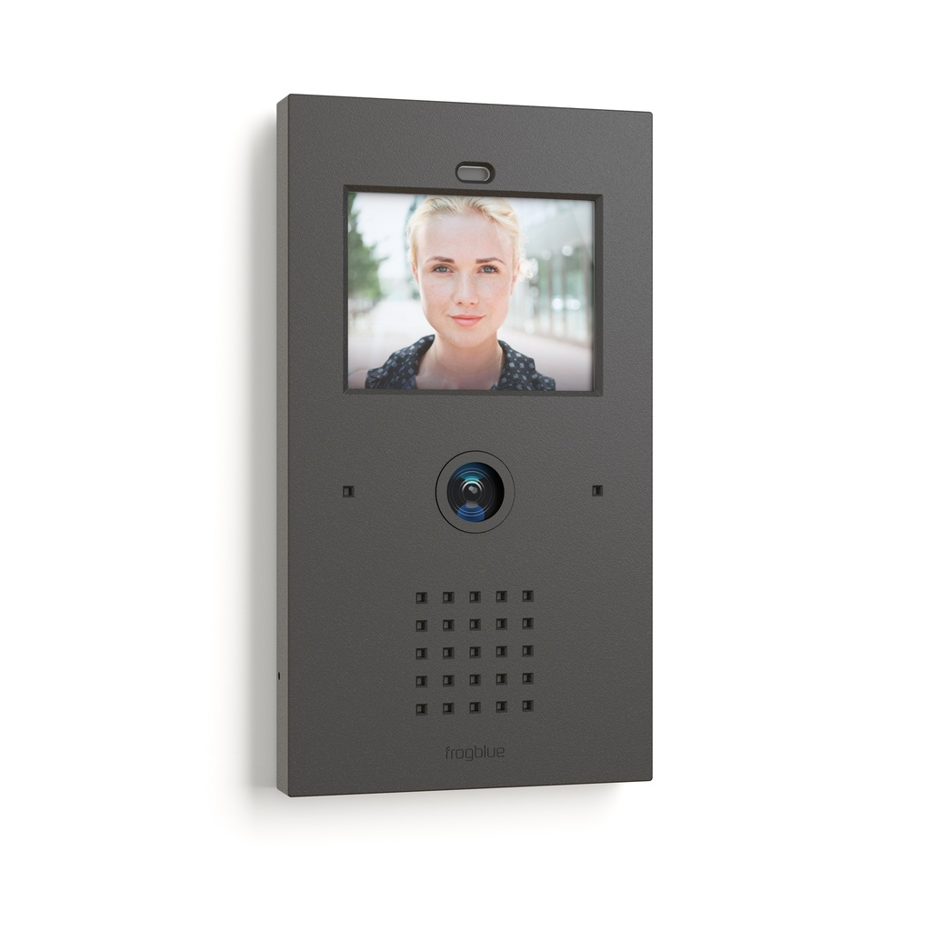
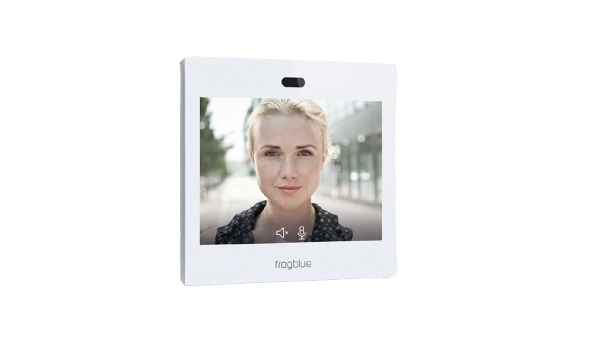
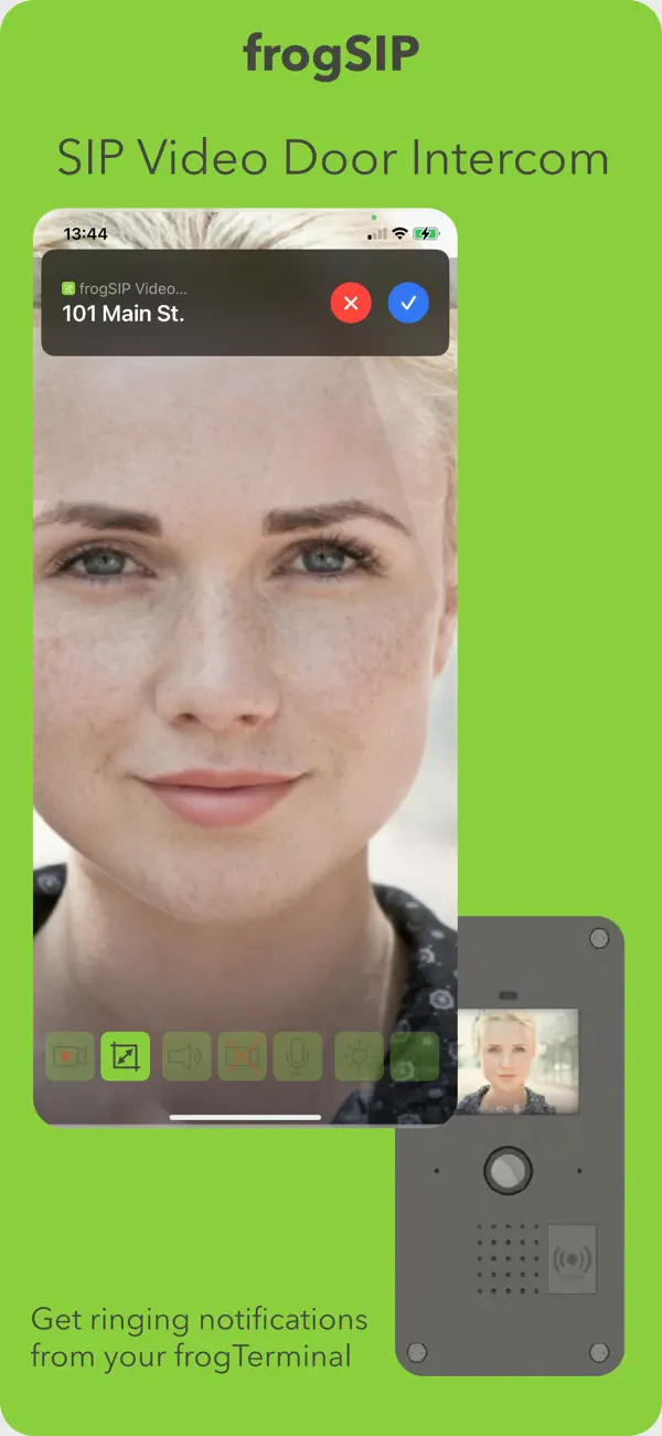 In this scenario, when the bell sign on the frogTerminal is pressed, the frogStation or frogDisplay rings. If the call is not answered, it is forwarded to the smartphone.
-
Configuration Steps Quick-recap:
-
frogTerminal: Add a bell sign (Technical Installation Manual, Section 7.1)
-
frogTerminal: Add bell action to call frogDisplay (Technical Installation Manual, Section 7.1.2)
-
frogDisplay/frogStation: Check frogDisplay / frogStation Settings (steps below)
-
frogTerminal: Add bell action for redirection (Technical Installation Manual, Section 7.1.8)
-
Pair your smartphone with frogTerminal (Technical Installation Manual, Section 5.6)
-
Configuration Steps:
-
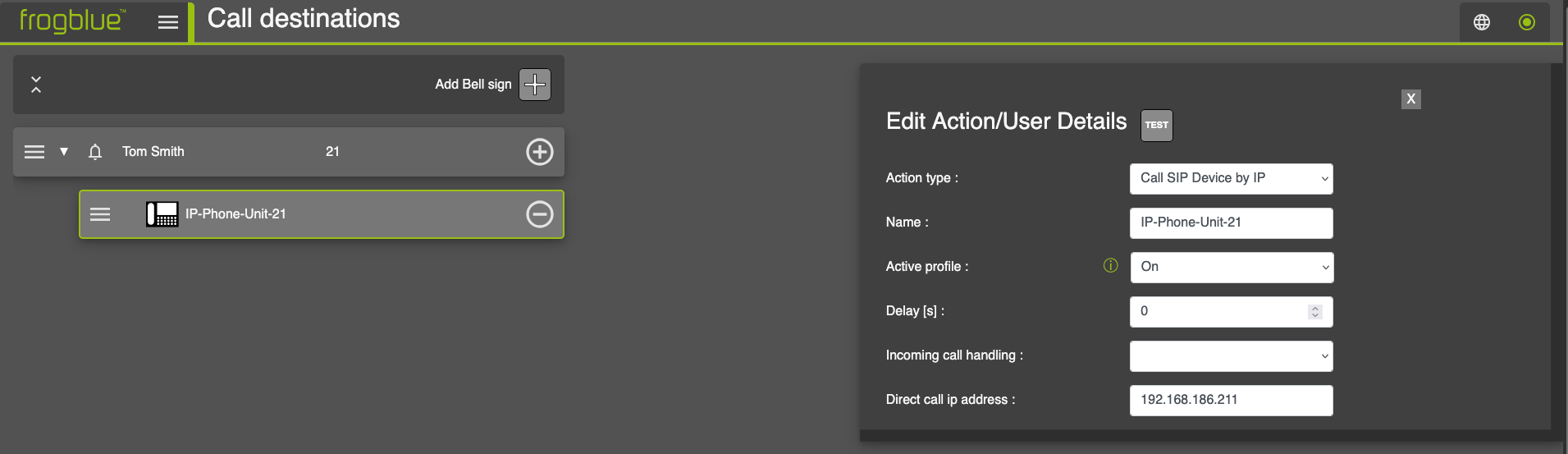
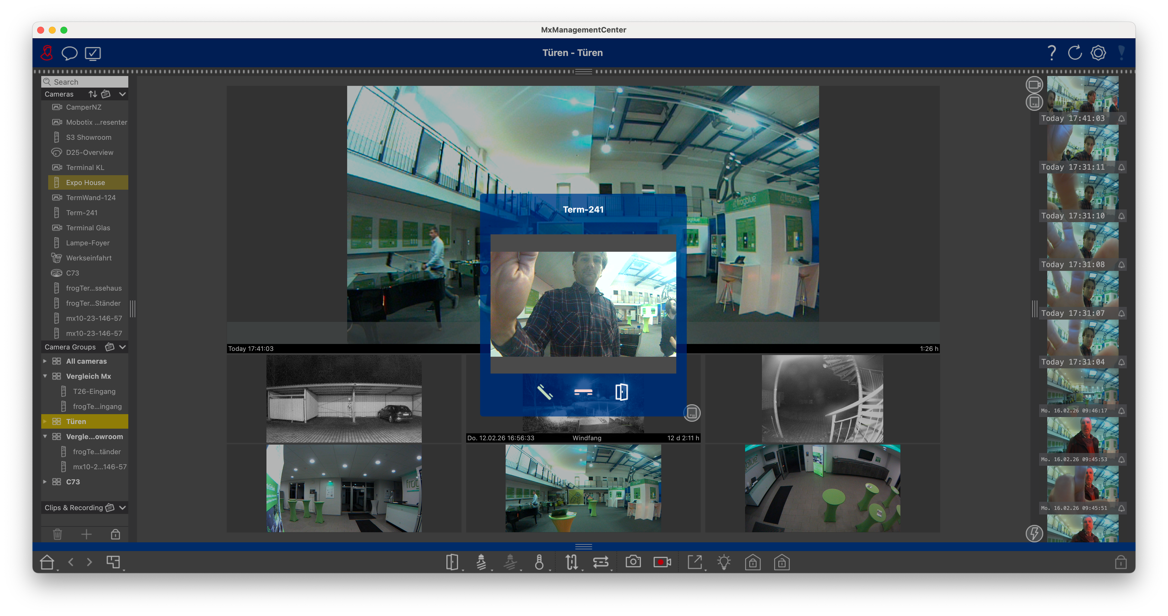
Steps 1 & 2: Open your web browser and enter the Terminal’s IP address to access the configuration interface. Then add a Bell Sign and configure an Action. Enter the IP address of your frogDisplay/frogStation in the field Direct call IP address. Direct call IP address. See Technical Installation Manual, Sections 7.1 and 7.1.2.
-
Step 3: frogDisplay / frogStation Settings: The frogDisplay/frogStation uses the following default settings. Please check that the settings still match your intended configuration:
 Step 4: From the Terminal’s Webinterface
follow the steps to add a bell action for redirection Technical
Installation Manual, Section
7.1.8.
Step 4: From the Terminal’s Webinterface
follow the steps to add a bell action for redirection Technical
Installation Manual, Section
7.1.8.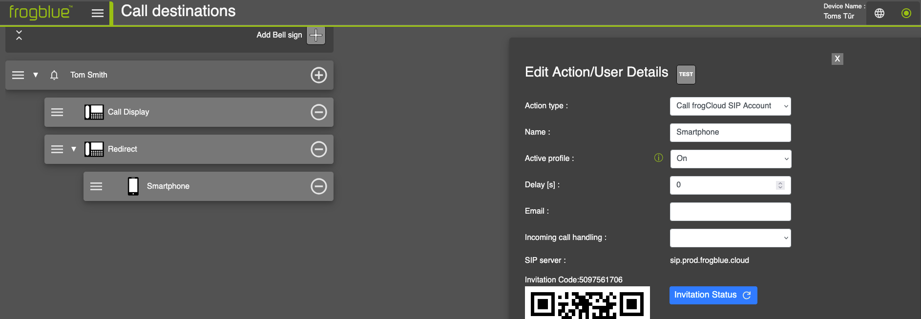
Step 5: To forward the call to a smartphone, add an additional bell action by clicking the “+” icon next to the contact (e.g. Tom Smith). Then select the desired Action type: Invite frogSIP Contact or Call frogCloud SIP Account. To pair your smartphone with the frogTerminal, please refer to the Technical Installation Manual, Section 5.6.
4. frogTerminal Integration to MOBOTIX Management Center (MxMC)
The frogTerminal integrates with MxMC via the EventStream on Port 8035.
To set up your frogTerminal with MxMC the following steps and settings
apply: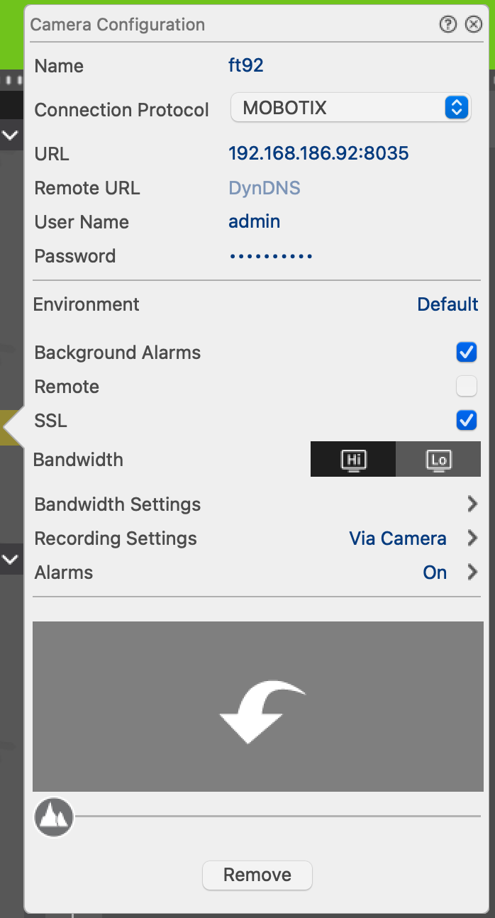
-
Open MxMC and add a new device
-
Enter a Name for your frogTerminal
-
Enter your User Name and Password
-
Check to enable Background Alarms (events)
-
Check SSL to use a secure connection
-
Save, Refresh, and trust the SSL certificate when prompted
-
For detailed information on integrating your frogTerminal into MxMC see Technical Installation Manual, Section 20.4.
5. Link frogTerminal and KNX
To link your frogTerminal to a KNX system, please first install the latest version of the frogOS firmware on your frogTerminal. Also integrate a KNX IP gateway into your KNX project. Furthermore, please ensure that all devices are on the same network and that the frogTerminal is integrated into a frogProject.
From KNX to frogTerminal
If, for example, KNX controls the light at the front door, a frogMessage can be sent as soon as the light is switched on there, which additionally switches the light in the stairwell.
Configuration - Quick overview
-
Read out the KNX group addresses
- Insert the KNX group addresses into the frogblue Event Management system
Step 1: To read out the KNX group addresses, ETS5 is used here, a manufacturer-independent standard software for configuring KNX building automation systems.
-
Start ETS5 und navigate to Topologie.
-
In the left panel, select the output to be switched (here: Output 1). The KNX group addresses will then appear in the middle window.
- In this example, we use 1/0/0.
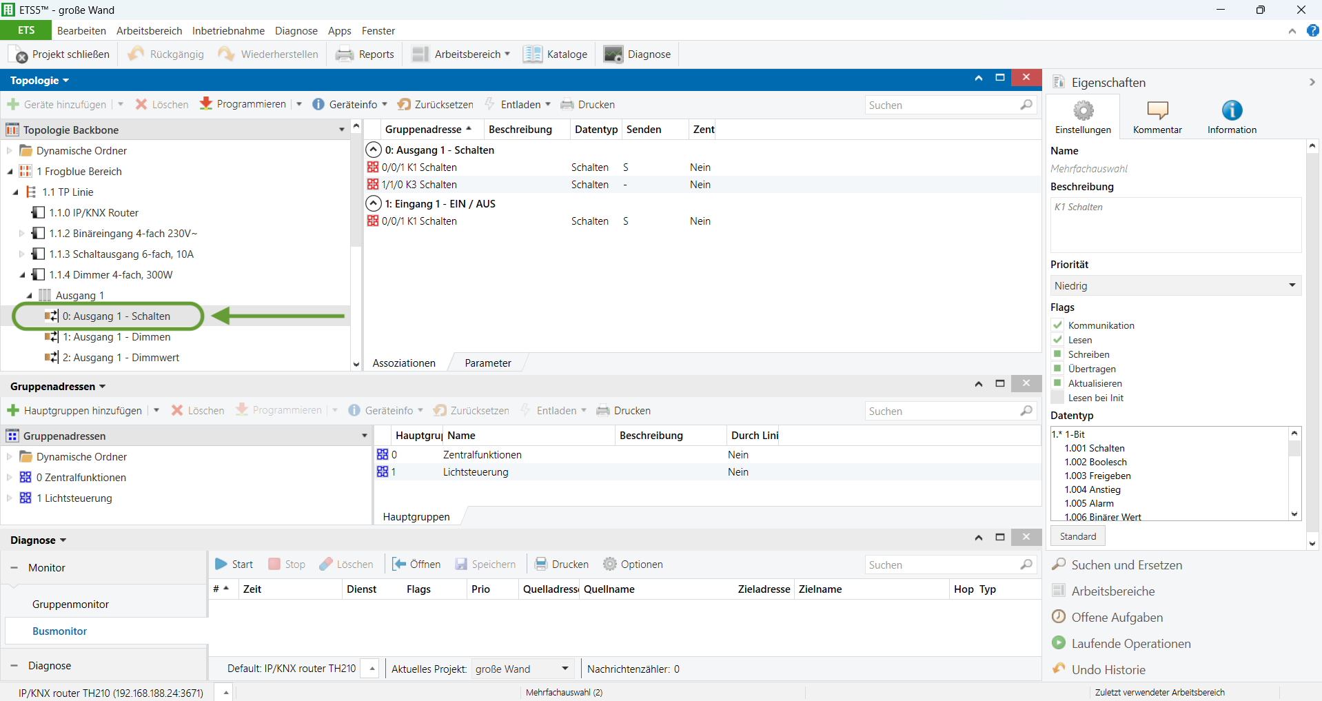
Step 2: Open your web browser and enter the IP address of the Terminal to access the configuration interface.
-
Navigate to Settings → Event Management
-
Add a KNX System Event: Select the Event Type KNX System Event from the drop-down menu and click the “+” button.
-
Use 1/0/0 as KNX group address.
-
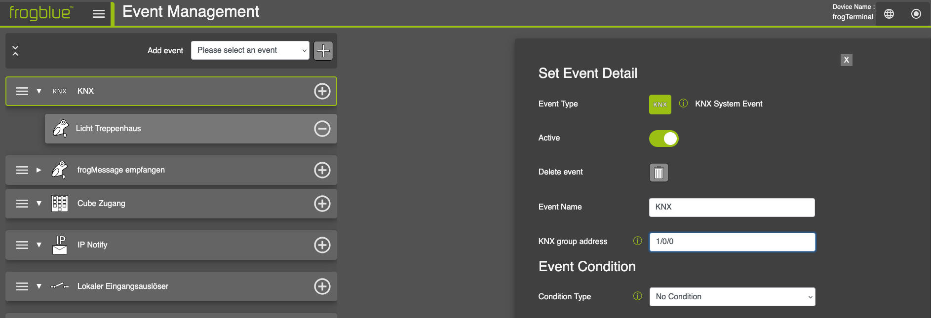
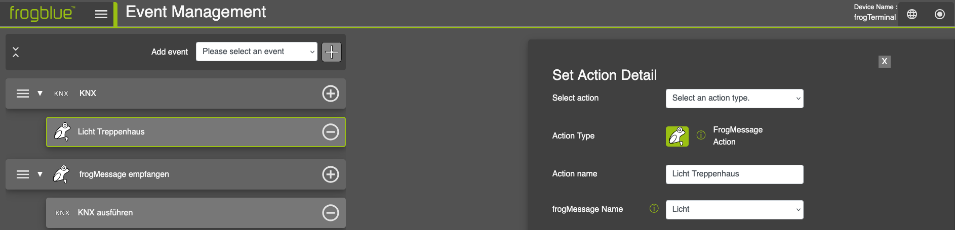
- With a click on the “+” symbol to the right of KNX, you can add a
-
frogMessage Action to the KNX event.
-
Select the corresponding frogMessage from the dropdown menu under
-
frogMessage Name.
-
From frogTerminal to KNX
-
For example, you can use our multifunctional transponder frogKey to remotely switch the KNX-controlled light at the front door.
-
Configuration steps:
-
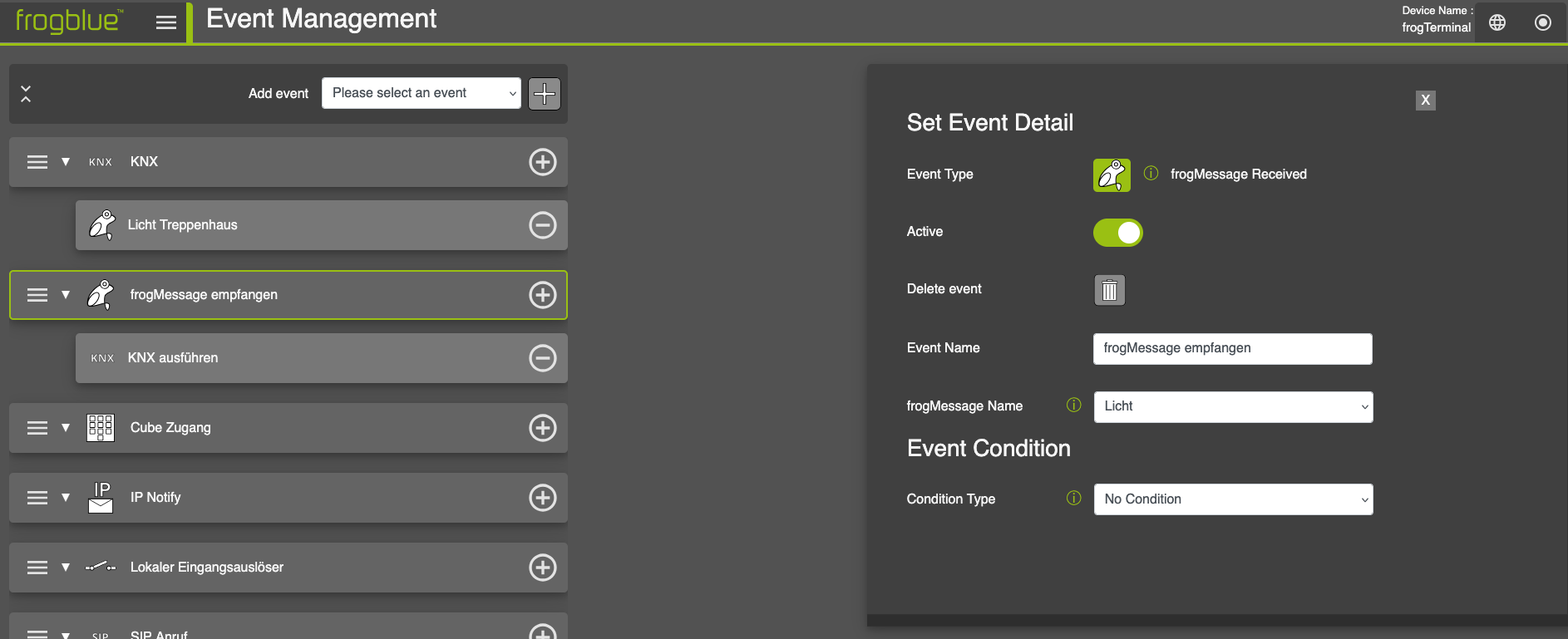
Set up the event Receive frogMessage in the Event Management of the frogTerminal.
-
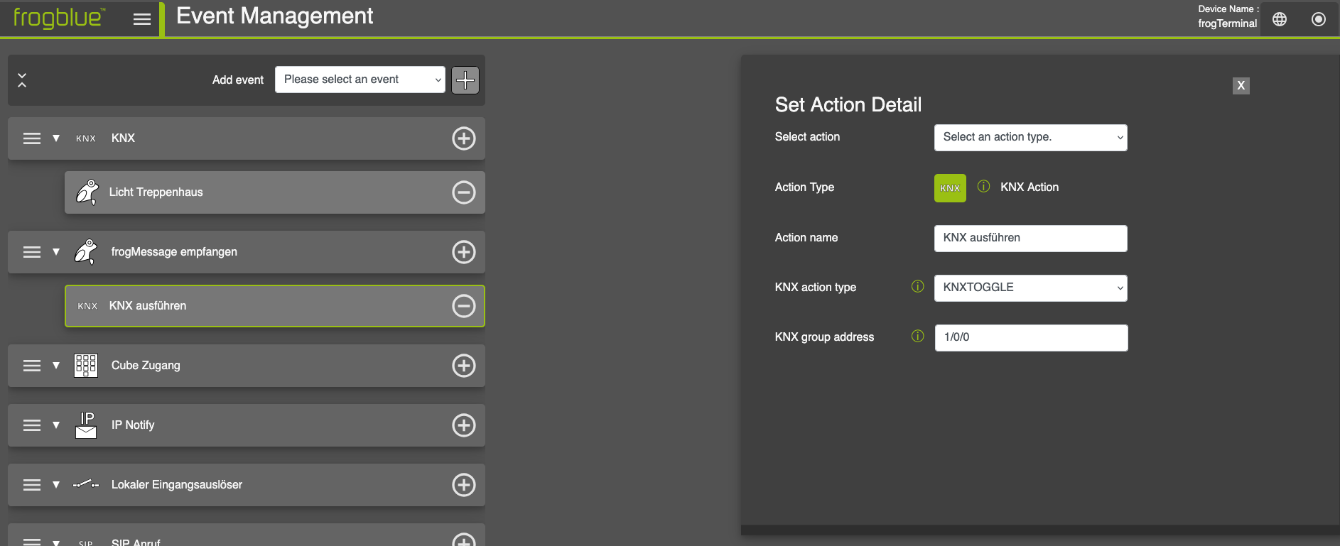
Add a KNX Action to the Event.
-
C. Technical Installation Manual
1. Introduction
1.1. Purpose of the Manual
- This manual provides step-by-step instructions for the installation, commissioning, and configuration of the frogTerminal. It is intended for professional installers, system integrators, and technical personnel responsible for deploying and maintaining the system.
- The manual covers mounting, wiring, network setup, access control, SIP telephony, video and recording management, as well as advanced functions and integrations.
1.2. Safety & Compliance
- Before installing and configuring the frogTerminal, read the following safety guidelines:
- Electrical Safety: Disconnect power before performing any wiring or maintenance.
- Secure Installation: Use strong passwords or keys for administrators. Ensure both side locking screws are secured. Consider flush-mount models to prevent unauthorised removal.
- Compliance: Ensure that the installation site meets all local electrical and safety regulations.
1.3. Tools & Equipment Required
- To complete the installation, ensure the following tools and materials are available:
- Drill and appropriate drill bits for mounting.
- Security bit or screwdriver (can be ordered separately - frogTerminal TM-Sec).
- Level and measuring stick / tape.
- Network cable (Cat 5e or higher, if using Ethernet).
- 8-Pin Phoenix Connector for network cable connection (included in box).
- PoE Switch/Injector or 12V-24V DC (or 24V AC) power supply.
- RFID keys, cards, or tags for testing access control functions.
- Laptop or tablet device for web-based configuration.
- Tablet (or Laptop + frogLINK) with frogProject App installed for configuring automation via Bluetooth (Recommended: iPad running iOS 12.1 or later).
- Smartphone or device with frogSIP App Installed for testing call functions.
- - Smartphone or device with frogControl App Installed for remote control and cloud automation functions.
- Note: A frogDisplay is currently required for remote control via the cloud when paired with the frogControl App for automation. Local control works directly as always.
- Terminal support is in development and will be included in a future software update.
1.4. System Overview
- The frogTerminal is a networked access control and communication device that integrates SIP telephony, video intercom functionality, credential based access control, and third-party system integrations.
- Key features include:
- SIP Telephony: Direct IP calling and multi-SIP server registration for advanced multi-tenant setups.
- Access Control: Decentralised credential management with encryption via PINs, Phone/NFC, RFID.
- Multi-Factor Authentication: RFID, PIN, Phone, video verification, and more via integrations.
- - Mesh Integration: Provides infrastructure-free communication using frogCast®, frogblue's unified BLE + IP Mesh technology.
- Cloud & Local Management: Supports remote administration via frogCloud and standalone operation for instant failover redundancy or completely private setups with VPN support.
1.5. Installation Workflow Overview
- Installation and commissioning of the frogTerminal follow these key steps:
- Pre-Installation Planning: Assess the mounting location, power, and network requirements.
- Physical Installation: Securely mount the device, connect power, and network cables.
- Initial Setup: Use the touchscreen wizard to configure initial admin credentials and network settings.
- System Configuration: Set up access control, SIP telephony, and integrations via the touchscreen or web interface.
- Testing & Verification: Ensure all functions, including door control and intercom, operate correctly.
- Final Deployment: Secure and backup configuration settings and inform end-users of operating procedures.
1.6. Support & Documentation
- For further assistance, refer to:
- The latest firmware updates and documentation at frogblue.com
- Technical support via authorised partners or your nearest frogblue CompetenceCenter.
- Online troubleshooting and FAQs.
2. Pre-Installation Requirements
2.1. Site Requirements
- Before proceeding with the installation, ensure the following conditions are met:
- Mounting Surface: Ensure the surface is stable and suitable for securely mounting the frogTerminal.
- Power Availability: Confirm the availability of PoE (Power over Ethernet) or a 12V-24V DC power source.
- Network Connectivity: A stable network connection must be available via Ethernet or Wi-Fi for full functionality. Standalone Automation & Access Control however, is supported even without network connectivity.
2.2. Power & Connectivity
- The frogTerminal supports multiple power, I/O, and network configurations with connectors for power, inputs, output, network, and additional expansion options:
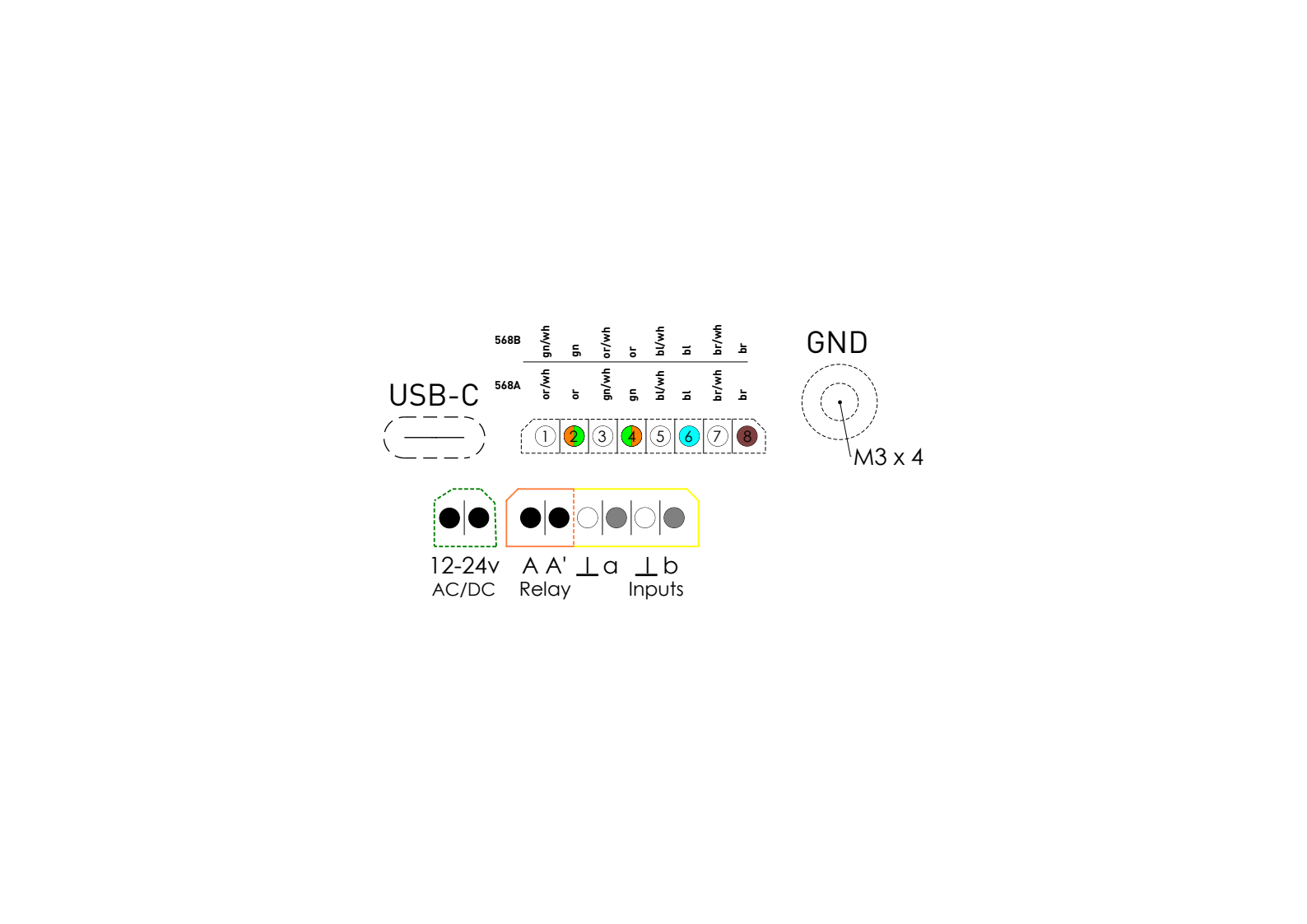
- Power Options:
- Power over Ethernet (PoE 802.3af, Class 3) via 8-Pin Connector (PTSM 0.5/8-P-2.5)
- 12V-24V DC external power supply via 2-Pin Connector (PTSM 0.5/2-P-2.5)
- 24V AC power source via 2-Pin Connector (PTSM 0.5/2-P-2.5)
- Standby consumption is approximately 5W.
- Network Options:
- Gigabit Ethernet for wired connectivity
- Dual-band Wi-Fi (2.4 GHz and 5 GHz, 802.11 b/g/n)
- Bluetooth Mesh for local frogblue device communication, automation & access
- Onboard Inputs & Output:
- Inputs: 2 x Potential-free contacts (self-supply 2 V / max. 1mA) Low voltage contacts (max. 30W / 50VDC)
- Relay Output: 1 x potential-free relay output (max load: 30 W / 50 VDC.)
- Additional Connections:
- M3 x 5 Grounding Screw Connector: Ensures proper earth connection and shielding for the PoE cable.
- USB-C Port: Reserved for future expansions or accessories.
- Connection Tips:
- Tighten screws securely on input/output connectors to ensure a stable connection.
- Ensure the ground screw is connected for safety and shielding.
- A small dab of non-permanent silicone adhesive can be applied to the sides of the phoenix connectors to keep them in place. Use a type that is easily removable for maintenance, such as neutral cure silicone, which won't damage the housing or connectors.
- For PoE setups, use a compatible network switch or injector that meets the 802.3af / class 3 standard.
2.3. Dimensions & Weight
-
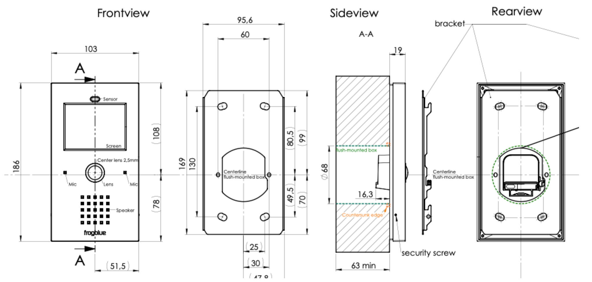
Dimensions: (L x W x H): 186 x 103 x 35.3 mm
-
Weight: 360g
-
Back Box Dimensions: Standard Ø 68 mm diameter for socket and switch installations (DIN 49073-1 / EN 60670-1).
-
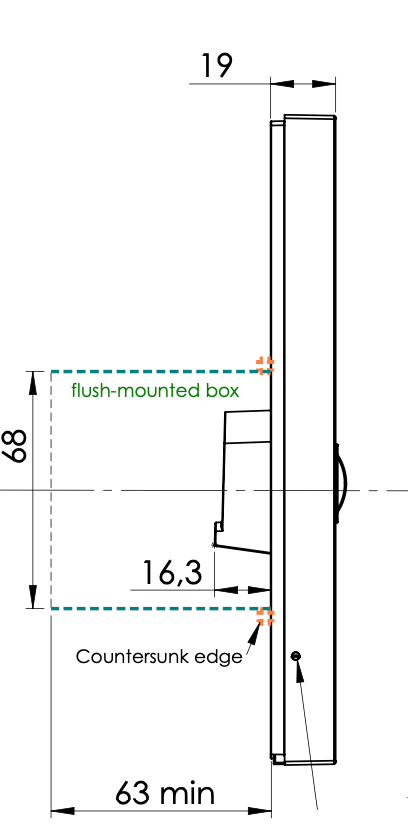
Minimum depth: 53 mm for installation in the back-box module. Recommended depth: 63 mm for optimal installation of the back-box module.
-
2.4. Installation Site Assessment
- Prior to installation, perform a site assessment to confirm:
- The optimal mounting height for ease of operation.
- The best network connection method (wired vs wireless).
- Sufficient clearance for device access and maintenance.
- Compliance with safety regulations and building codes.
- Telephony Assessment:
- Multi-tenant setup: Verify communication options (SIP, DECT, or PSTN phone systems).
- Smartphone compatibility: Confirm availability of smartphones running frogSIP Apps.
- Cloud/Internet connectivity: Ensure remote telephony capabilities if required.
2.5. Required Components for Installation
- Ensure all required components are available before installation:
- - frogTerminal with up-to-date firmware or frogOS file ready before deployment see frogblue.com → Support → Software.
- Mounting bracket and screws (included in the box).
- Power source (PoE injector, DC power adapter, or AC power connection).
- Network cable (Cat 5e or higher for Ethernet setups).
- RFID cards or key fobs (if access control functionality is required).
2.6. What’s in the Box
- For the models: frogStation KL, frogTerminal KL, frogTerminal Glas, and frogTerminalALU. The following items are included in the box:
- Package insert sticker with serial, barcode, version information.
- frogTerminal, Aluminium mounting plate with attached gasket seal.
- 4 × screws (Ø4.5 × 40 mm).
- 4 x Insulation fixings - plastic spiral dowels or "anchor plugs".
- 4 × dowels or "anchor plugs\" (UX6).
- 1.5 mm hex key (for locking side screws).
- 2-pin, 6-pin, and 8-pin Phoenix plug connectors (for power, I/Os, and Ethernet).
- 1 x RFID frogblue Card
- Package leaflet with operating instructions.
3. Physical Installation Process
3.1. Mounting the Device
- Steps:
- Mount the terminal.
- Connect power (PoE or external).
- Wire inputs/outputs for relays or buttons.
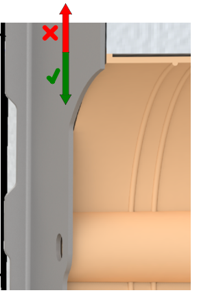
3.1.1. Standard Surface-Mounted Installation
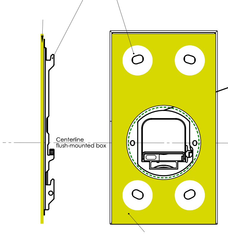
Standard steps for an on wall surface-mounted installation with the following frogTerminal models: frogStation KL, frogTerminal KL, frogTerminal Glas, and frogTerminalALU.
Prepare a recess with a minimum depth of 53 mm (recommended 63 mm) and a Flush- mounted junction box.
Screw the mounting plate/bracket onto the flush-mounted box using the 2 screws.
Align the plate and mark the 4 screw holes (use the holes as a template).
Remove the mounting plate/bracket and drill the 4 holes.
Insert the dowels or "anchor plugs" (UX6). If fixing to insulation e.g. Styrofoam, use the included insulation Anchors (larger spiral type dowels).
Fix and align the mounting plate/bracket using the 2 device screws (included in the box).
Secure the mounting plate/bracket by screwing in the 4 included screws (Ø4.5x40) into the previously installed plugs (UX6).
Connect the cables to the Terminal KL (PoE cable, Ground screw, Power, Inputs & Output).
Ensure proper grounding (use the extra screw in the back panel).
Place the Terminal KL onto the mounting plate/bracket and slide it down until it clicks into place.
On the left and right sides of the door station, use the hex screwdriver to tighten the set screws, securing the door station against theft. Turn the screws anti-clockwise to activate the theft protection and clockwise to release it.
3.1.2. Flush-Mounted Installation
Prepare the recess in the wall following the specified dimensions.
Insert the flush-mount box and secure it with screws.
Mount the frogTerminal into the box and align it properly.
3.2. Connecting Power & Network
If using power over Ethernet (PoE), connect the Ethernet cable to a PoE switch or injector that complies with 802.3af / Class 3, and to the Terminal with the 8-Pin Phoenix connector.
If using a 12-24V DC or 24V AC power adapter, connect the leads with the 2-pin Phoenix connector to the Terminal.
Verify the Terminal boots up into the Start Wizard screen or a preconfigured user interface indicating proper operation.
Connection Tips:
Tighten screws securely on the Phoenix connectors.
A small dab of non-permanent silicone adhesive (neutral cure silicone) may be applied to stabilise the connectors.
4. Initial Setup & Configuration On-Device Touch Screen Installation Wizard
The on-device wizard simplifies the initial configuration of the frogTerminal, walking you through the essential settings step by step. This section ensures a smooth installation experience, even for users with minimal technical expertise.
The wizard can be accessed again at any time with a factory reset. Currently in development, sections of the wizard will be directly accessible—allowing you to repeat specific steps, such as cloud registration, smartphone pairing, or other key configurations.
Steps Overview:
Configure localisation settings: language, date, and time.
Secure the interface setting an Admin PIN for configuration via the touch-screen interface and a Web Password for remote administration via a browser.
Set up network settings & frogBlue Mesh.
Register the terminal with SIP/cloud services.
Configure call bell settings.
Complete the setup and test the device.
To start the Installation Wizard: Power on the device & tap “Start Wizard”.
| Step | Description |
|---|---|
| 1 | Tap Start Wizard. |
4.1. Installation Wizard Step 1: Set Language and Timezone
| Step | Description |
|---|---|
| 1 | Tap on the dropdown menus to choose your preferred language and timezone. Tap the arrow to proceed. |
4.2. Installation Wizard Step 2: Define the Admin PIN
| Step | Description |
|---|---|
| 1 | Tap the first key icon. |
| 2 | Enter your chosen 6-digit Admin PIN number using the on-screen keypad and tap to confirm. |
| 3 | Tap the second key icon. |
| 4 | Enter your 6-digit Admin PIN number once more and tap to confirm. |
| 5 | Tap the next arrow to proceed. |
4.3. Installation Wizard Step 3: Set the Web Password / HTTPS Admin Password
| Step | Description |
|---|---|
| 1 | Tap on the light-grey Password text input field (right side). |
| 2 | Using the on-screen keyboard enter your chosen password for the admin user. |
Note: Passwords must be at least 8 characters long and include at least one uppercase letter, one lowercase letter, and one number.
Note: Make a note of or record your specified web password, as it will be required later to administer the Terminal through a web browser.
- The factory default login credentials for accessing the camera via web browser are:
- Username: admin
- Password: frogblue
| Step | Description |
|---|---|
| 1 | Tap the next arrow to proceed. |
4.4. Installation Wizard Step 4: frogBlue Mesh Setup
| Step | Description |
|---|---|
| 1 | Tap the drop-down arrow (top right). |
| 2 | Tap your desired option. Either tap the next arrow, or enter the Project Key and tap the next arrow to proceed. |
Lock the BT Interface: The frogblue Mesh is locked and needs to be unlocked by performing a factory reset see section 20.2 „System Control - Manage configuration files, Reboot, and Factory Reset".
- Set Project Key: The frogblue Mesh is encrypted and you set the Project Key in the next step - frogBlue Mesh functionality is ready to use and the frogTerminal can be integrated into a project with this specified Project Key.
- No change (open): The frogblue Bluetooth Mesh remains open and unencrypted. Anyone with the frogProject App or configuration tools can commission the system via Bluetooth.
- Warnung!: When selecting "No change (open)", the system remains insecure until the configuration has been completed and the Terminal has been commissioned (e.g., with the frogProject App).
4.5. Installation Wizard Step 5: Set Device Name
| Step | Description |
|---|---|
| 1 | Tap the text area “Main Door” and use the on-screen keyboard to enter a name for your Terminal. Tap the next arrow to proceed. |
4.6. Installation Wizard Step 6: Set the Home Screen Layout
Define the Home Screen Layout, the default view displayed when the Terminal is on standby and ready to be activated by touch, proximity, motion, input, etc.
Note: Currently in development with a software update currently under development, the Home Screen will feature customisation options for images, logos, styles, search functionality, and scrollable call lists.
Preview:
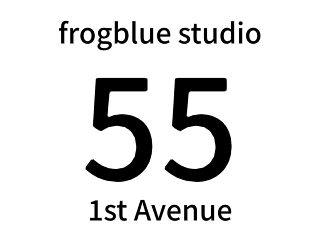
4.7. Installation Wizard Step 7: Connect frogTerminal to your physical or Wi-Fi Network
| Step | Description |
|---|---|
| 1 | Tap on the icons to configure the Ethernet and Wireless Interface Settings. |
Ethernet Configuration:
| Step | Description |
|---|---|
| 1 | Leave Active or deactivate Ethernet via the toggle switch if using Wi-Fi. Tap the lines to modify IPv4 address or DNS Settings. Tap the back arrow to return, or the save icon to save changes and return to the Network Setup Page. |
Wi-Fi Configuration:
| Step | Description |
|---|---|
| 1 | Ensure 2 green ticks for Connection and frogCloud. Tap Next to continue. |
Note: If you experience connectivity problems see section 5.1.5 Troubleshooting Network Connectivity Problems.
4.8. Installation Wizard Step 8: Connect to frogCloud
| Step | Description |
|---|---|
| 1 | To add to an existing or to create a frogCloud project for this installation, tap Login to frogCloud. To register a new frogCloud account and create a new frogCloud project for this installation, tap Register a frogCloud account. To proceed with a custom or advanced setup without the free frogCloud service, tap Skip frogCloud and proceed to Section 4.16. |
- For quick and easy connectivity with a smart device, a frogCloud account is recommended.
- Note: A confirmed email is required for frogCloud. Create and manage accounts via the frogSIP App (iOS/Android) or at frogblue.cloud/login.
4.9. Installation Wizard Step 9: Login to or register for a frogCloud Account
Login to an existing frogCloud Account:
| Step | Description |
|---|---|
| 1 | Tap on the text areas E-Mail and Password. Use the on-screen keyboard to enter your existing frogCloud account credentials. Tap Next to continue. |
Register for a new frogCloud Account:
| Step | Description |
|---|---|
| 1 | Tap on the text areas E-Mail and Password. Use the on-screen keyboard to enter your email address and a password of your choice for your frogCloud account. Tap Next to continue. |
4.10. Installation Wizard Step 10: Confirm account activation E-Mail
| Step | Description |
|---|---|
| 1 | Wait for the following message confirming that an E-Mail has been sent to your address. Check your E-Mail, click the link, then login with your username and password to activate your new frogCloud account with SIP call functionality. Tap Next to continue. |
Open your email inbox, click the provided confirmation link, and log in with your email and password to activate your frogCloud account with SIP call functionality.
4.11. Installation Wizard Step 11: Create Cloud Project
| Step | Description |
|---|---|
| 1 | Wait for and ensure green ticks for each item indicating a successful connection to frogCloud, project creation, Terminal SIP account creation, and successful SIP telephony connection. Tap Next to continue. |
4.12. Installation Wizard Step 12: Create Bell Buttons
| Step | Description |
|---|---|
| 1 | Tap “Tom Smith” and use the on-screen keyboard to enter a name label for your first Bell Button. Tap Next to continue. |
4.13. Installation Wizard Step 13: Pair with smart device
| Step | Description |
|---|---|
| 1 | Use your smart device with the frogSIP App to enter the Invitation Code or scan the QR Code to pair with your Terminal. Once paired you can initiate a test call by tapping the Test Call button. When finished, tap Next to proceed. |
4.14. Start View and View Modes Explained
The Start View appears when the Terminal is activated via proximity detection or touch. Views are made up by a main area and a toolbar. The system supports 4 view modes with further customisation of the toolbar possible via the Web Browser.
Toolbar buttons:
 Enables the entry of Function PINs.
 Opens the Camera dialog. Refer tosection 8 „Camera Settings and Recording Management" for details on configuring in-stream settings.
 Opens the on-device touch screen configuration and administration pages.
 Enables calling by Apartments or Unit numbers. NOTE! Works only when numbers have been defined for each call entry in the Apartment field in Settings → Call destinations.
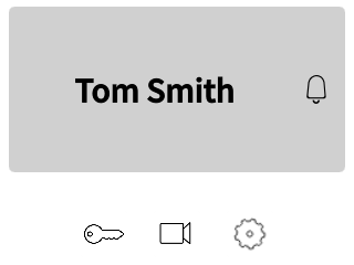
View Mode 1. Bell Buttons:
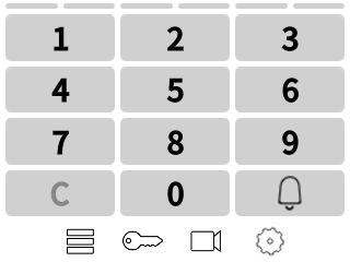
This view provides Bell Buttons in the main area and 3 Toolbar Buttons.
View Mode 2. App + Pins:
This view provides PIN code and apartment / unit number entry in the main area and 4 Toolbar Buttons.
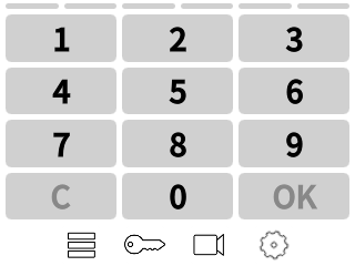
View Mode 3. PINs:
This view provides PIN code entry in the main area and 3 Toolbar Buttons.
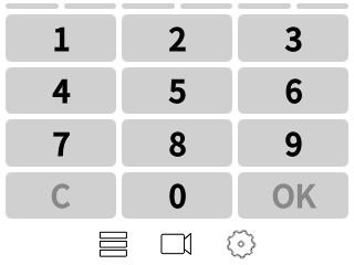
View Mode 4. Apartment:
This view provides apartment / unit number entry in the main area and 4 Toolbar Buttons.
4.15. Installation Wizard Step 14: Start View
| Step | Description |
|---|---|
| 1 | Select your desired Start View. Tap Next to continue. |
4.16. Installation Wizard Step 15: Finalise Wizard
| Step | Description |
|---|---|
| 1 | You’re all set! The welcome screen appears, confirming the Wizard’s completion. Tap Next to proceed. |
Wizard Complete!
Congratulations on completing the frogTerminal Installation Wizard! You can now make calls using the Bell Button (e.g., "Tom Smith"), trigger Function PINs
and access the on-screen camera
and system setup pages
using your Admin PIN.
5. frogSIP App User Interface
5.1. Introduction to frogSIP
The frogSIP app serves as the primary interface for managing and interacting with frogTerminal devices. This section provides a step-by-step guide on pairing the app with frogTerminal, configuring user settings, managing security logs, and reviewing call history.
5.2. Welcome Screen Overview
- Upon launching the frogSIP app, users are presented with the Welcome Screen. The interface will automatically match the language of the smartphone device. To change the language tap the Burger Menu → Settings → General → Language and select your desired language.
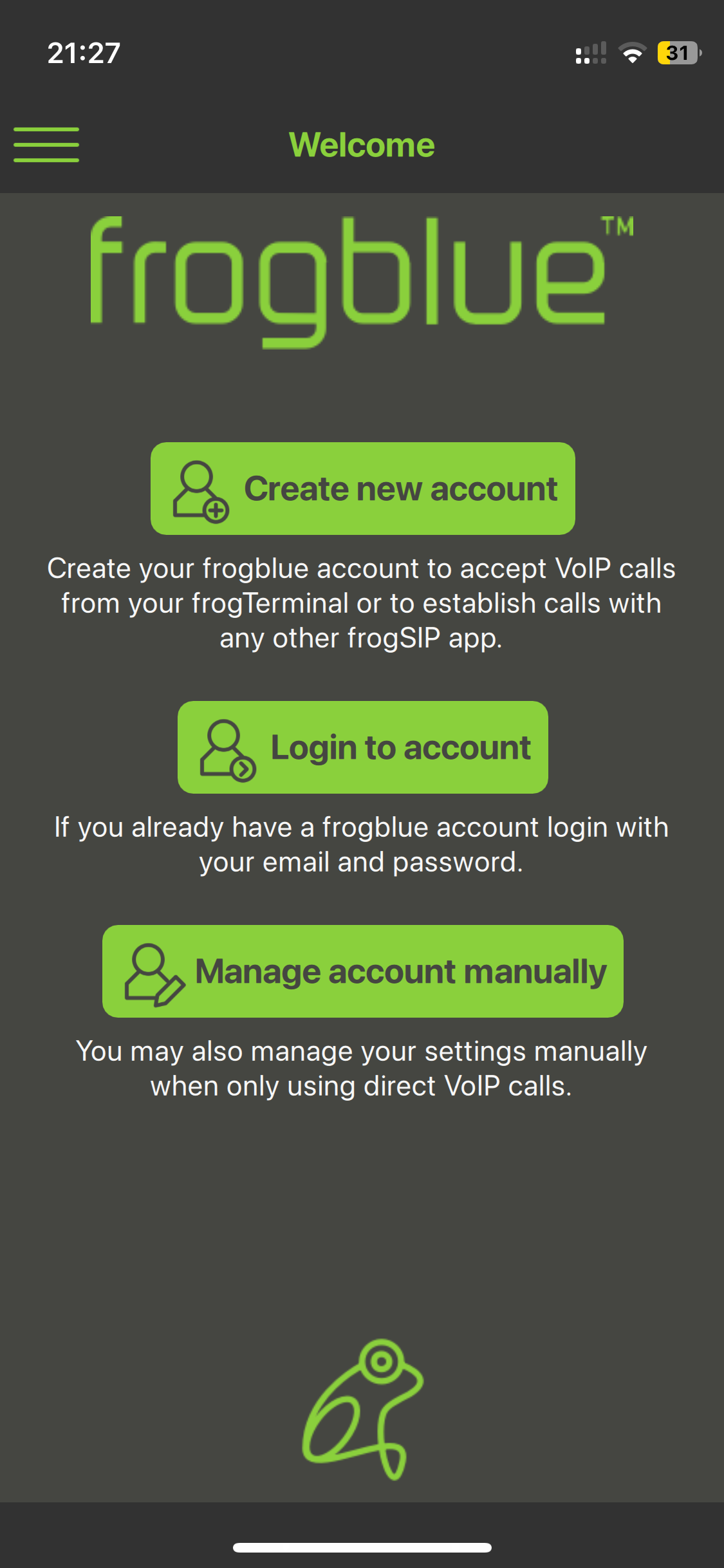
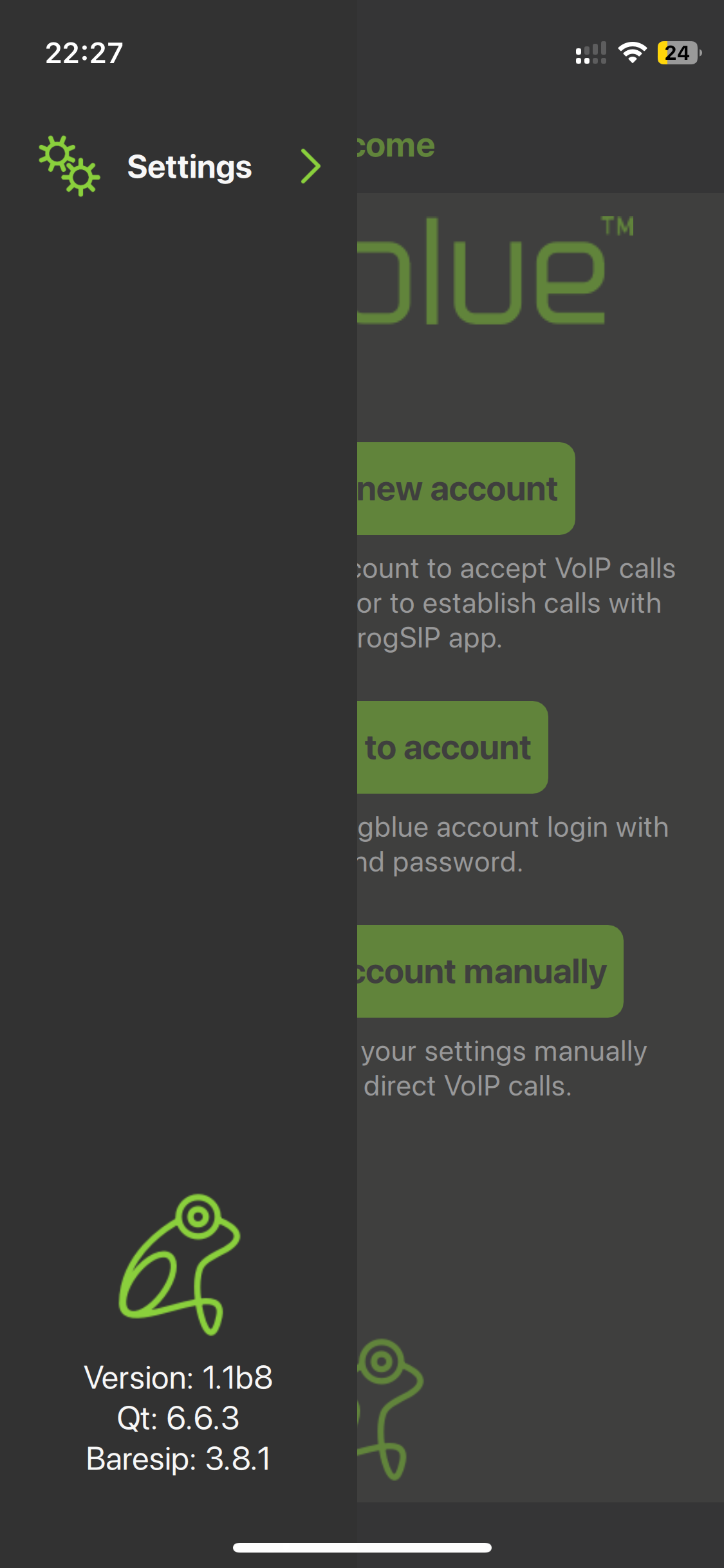
- - Note: To begin we will cover creating and logging into frogCloud accounts. Manage account manually is used for custom SIP integrations and covered in a later section.
5.3. Create a new frogCloud user account from the frogSIP App
| Step | Description |
|---|---|
| 1 | Tap Create new account. |
| 2 | Enter your information: User name: The user and display name for this frogCloud user account. Email: Enter and repeat the email address associated with this frogCloud user account. Password: Enter and repeat a password for your frogCloud user account. Tap Register. |
| 3 | Wait for the following message confirming that an E-Mail has been sent to your address. Check your E-Mail and click the link to open the frogCloud login screen in your web browser. Login with your username and password to activate your account. |
| 4 | Wait for the following message confirming that your new account is activated. Tap Continue. |
- This section guides you in creating a frogCloud account from the frogSIP app Welcome Screen.
- If you've skipped the welcome screen and wish to return simply tap the Burger Menu → Account → Logout, then tap Logout again to confirm.
If you receive any error ensure the following:
- Your frogTerminal is updated to the latest frogOS version, available from frogblue.com.
- Your frogSIP App is also updated to the latest version.
5.4. Login to the frogSIP App with an existing frogCloud user account
| Step | Description |
|---|---|
| 1 | Tap Login to account. |
| 2 | Enter your information: Email: Enter the email address associated with your frogCloud user account. Password: Enter the password for your frogCloud user account. Tap Login. |
| 3 | Wait for the following message confirming that your account is activated. Tap Continue. |
If you're logged in and want to log out, tap the Burger Menu → Account → Logout, then tap Logout again to confirm.
5.5. Main App Interface Overview
The frogSIP App provides a streamlined interface for managing SIP-based video intercom and access control systems. The user interface is designed for efficiency, with a slide-out sidebar for quick access to key functions.
Touch-Friendly Design for mobile and tablet usage.
Dark & Light Mode Support for better visibility in different environments.
Multi-Language Support for international deployments.
Real-Time Notifications for call alerts, access logs, and system events.
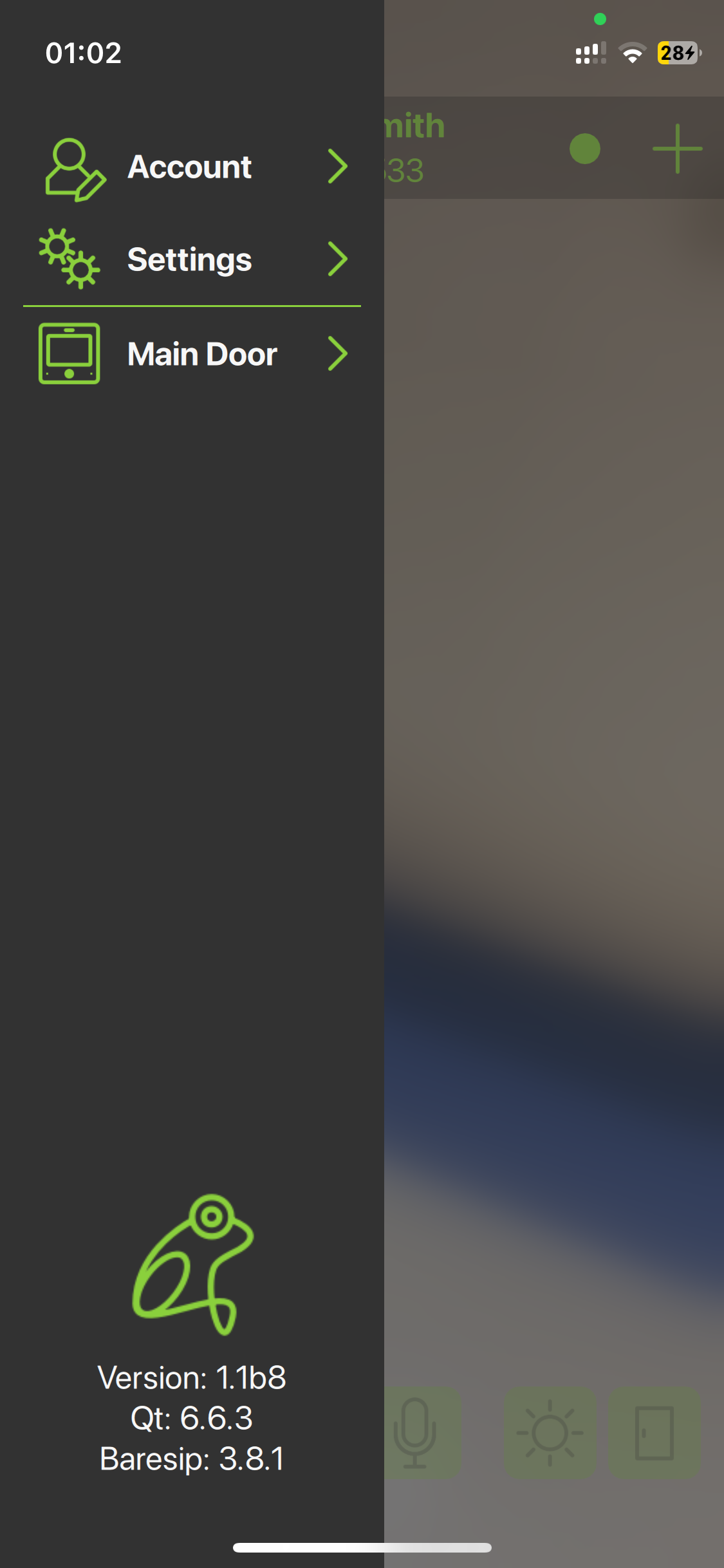
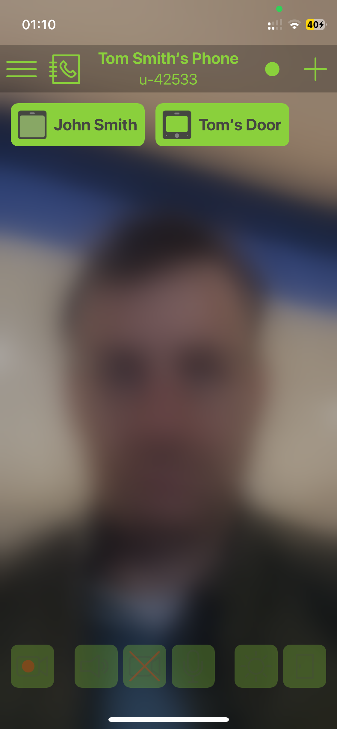 The main view consists of the following sections:Details:
Open Sidebar (Burger Menu): Toggles the slide out sidebar, to provide quick access to account, app, and door terminal settings.
Slide-out Sidebar:
Account Settings: Manage your frogCloud account.
App Settings: Manage user & password settings, logout, or delete your account.
Door Terminals: View a list of Terminals paired with the App.
Version Information: Access details about the versions of the App and its bundles.
Phone Call Directory: Quickly call any paired users or devices from a call directory.
Header and Phone Information: Displays standard iOS/Android device details.
User Name: The username associated with your frogCloud or SIP account.
frogCloud connection Status:
Undefined
No connection
Connected
The connection status indicator displays the link between the App and frogCloud. A green light means the connection is active, red indicates that there is no connection, and grey signifies that the App is not properly configured.
Add remote Station or User: Quickly add or pair with a new remote station or user.
frogCloud ID / SIP username: Your frogCloud ID or SIP authorisation username.
Favourites / Call shortcuts: Quick-access buttons for calling your favourite
Main View: The smartphone camera is blurred by default when not in a call. To disable the blur, go to Burger Menu → Settings → Appearance and toggle “Blur camera self-view.”
Toolbar: Active During Calls with a frogTerminal. Access controls for enabling/disabling video and microphone, and quickly view recordings, logs, lights, and door controls.
5.5.1. In-Call Toolbar

-
Logs & Playback: Review access & bell logs, and video playback of recordings.
-
Speaker-mode: Toggle speaker-mode for hands-free communication during calls.
-
Audio/Video: Enable or disable the sending of audio and video from your device to the Terminal.
-
Lights: Control the Terminals “Light” HomeObject.
-
Doors & Openers: Control the Terminal’s door openers.
-
5.5.2. Logs & Playback Toolbar
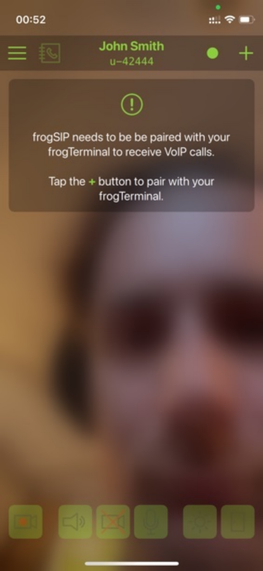
-
Logs & Playback: Toggles between the research player view—used for video recording playback and reviewing access or event logs—and the live call view.
-
Earliest Event: Jump to the earliest recorded event in the system.
-
Play Event: Plays back the recording sequence if more than one frame has been recorded for this event.
-
Last Event: Jump to the last recorded event in the system.
-
Next Event: Jump to the next recorded event in the system.
-
Prior Event: Jump to the previous recorded event in the system.
-
| Step | Description |
|---|---|
| 1 | On your Dashboard, tap Alarms. |
| 2 | Tap on the alert lines. |
| 3 | Tap on the bell icon. |
| 4 | Tap and hold the play icon to select your preferred alarm sound. |
| 5 | Click on the name to select the sound. The selected sound appears green. |
| 6 | Ensure that the alarm icon is active (i.e. blue). |
| 7 | Swipe to the left and select the phone icon. |
| 8 | Edit the profile name. Set the number of repetitions of the sound signal. Set the break time between the repeated sound signals. Adjust the volume of the sound signal. |
5.6. Pairing the Terminal with frogSIP App
| Step | Description |
|---|---|
| 1 | Tap the + Icon Add remote Station on the top right. |
| 2 | The Terminal can be paired in 2 convenient ways: Via QR-code: Ideal for quick and easy pairing when the smartphone running frogSIP is in the same location as the Terminal during the Wizard setup. Via Invitation PIN: Useful for remote pairing when the installer or admin is not on-site. |
| 3 | Use your smartphone camera to scan the QR code displayed on the frogTerminal device screen. Once the device name appears on the screen and the Accept button turns solid green, the QR code has been scanned successfully. Tap Accept. |
| 4 | When you see the message “The invitation has been accepted …”, your Terminal and frogSIP App have been successfully paired. You can now tap Continue. If you receive an error, such as “The invitation code is not valid for this version! …”, ensure the following: Your frogTerminal is updated to the latest frogOS version, available from frogblue.com. Your frogSIP App is also updated to the latest version. |
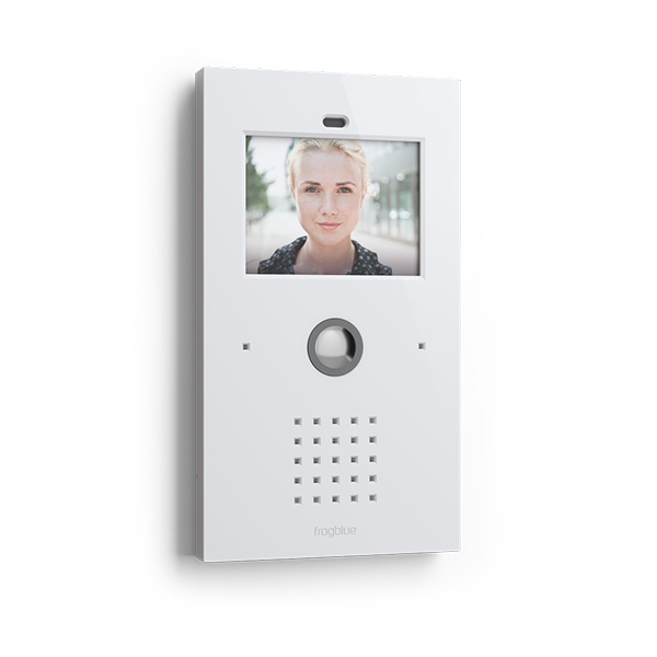
In this section, you’ll learn how to pair your terminal with the frogSIP app on your smartphone. You can complete the pairing process either by entering a pairing PIN code or by scanning a QR code via frogCloud. This secure connection ensures seamless integration, enabling you to efficiently manage calls and configure settings from your mobile device.
frogCloud makes pairing and connecting multiple sites and door Terminals a breeze.
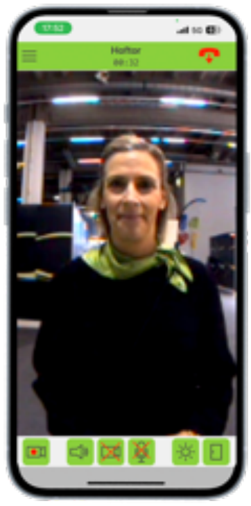
Call, Playback, and Manage frogTerminal with frogSIP
This section details how to use frogSIP with your frogTerminal. It covers initiating calls, accessing and reviewing recordings, and managing device settings.
5.7.1. Receiving calls
Receiving calls is as simple as answering a phone call. After pairing with the Wizard, calls to your smartphone work automatically. For further configuration, see section 7 „Telephony Call Destinations Setup". Calls can be received with frogSIP or from a frogStation, frogDisplay, SIP Phone, or of course another frogTerminal.
Once call is connected, the interface is identical to that of initiated calls—the following sections detail the interface for both initiated and received calls.
5.7.2. Auto Answer Configuration
For the frogTerminal to automatically answer calls from authorised users, ensure Max auto answer level for users is set to Automatic answering from Web → Settings → General. Additionally, users can be restricted to audio-only or full audio/video access via Web → Call Destinations → Bell signs.
5.7.3. Initiate calls
| Step | Description |
|---|---|
| 1 | Tap the Call Directory or select from your Favourites to initiate a call with your frogTerminal. |
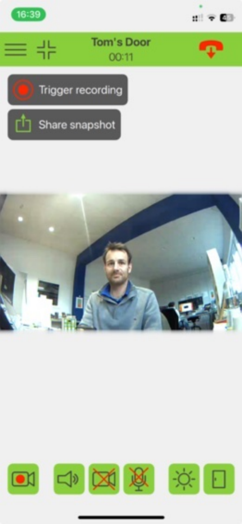
| 2 | To take a picture or trigger recording from a call tap the camera icon to see the following options. Trigger recording: Triggers a recording via the user click event in the frogTerminal. Manually starts the recording of 1 event. Go to Settings > Recording to check and modify recording settings. Share snapshot: Take a current still image from the Terminal and share it via your smartphone sharing options. |
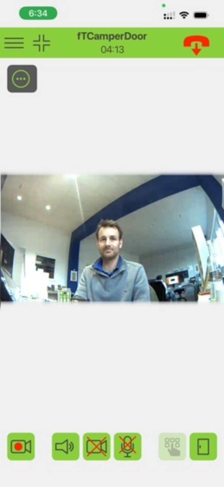
| 3 | Hide toolbar: Hide the toolbar to provide more space for the video call. Trigger recording: Trigger a manual recording from within the call. Hangup: Hangup the call. Quick menu: Open the quick menu to take a picture or trigger recording from a call. Light: Toggle on/off the light. Door: Open the door - when multiple doors are configured another dialog appears allowing you to see the door states and choose which door to open. |
Once a call is connected, the toolbar appears. To enable the video toggle before the call connects, go to Burger Menu → Settings → Video and turn on Allow early video. This setting lets you activate your video feed before making a call.
Door states dialogue
box:
5.7.4. Access & Event Logs and Playback from a frogSIP call
| Step | Description |
|---|---|
| 1 | Tap the Logs and Playback button (Bottom left). Filter events by type or date range using the lower toolbar. Tap an event to play back its associated video recording in the same view, and use the playback controls to navigate between events. |
Terminal Settings
5.9.1. Bell Button Settings
| Step | Description |
|---|---|
| 1 | After clicking on Bell settings, a dialog opens where you can: change the name displayed on the bell sign, activate or deactivate the bell sign, and set the bell sign to visible or invisible. |
5.9.2. Access Control Settings with PIN
| Step | Description |
|---|---|
| 1 | After selecting RFID settings in the main menu, the corresponding dialog opens. For Terminal settings see 6.8.1. RFID Encryption and Zones Via Web Browser (Terminal Settings). Under RFID cards, all persons with stored RFID cards are listed. |
| 2 | Change the RFID settings for users who have already been created: Name, PIN-code, Zones, Validity period of the RFID card (Valid from and Valid until). By clicking on the calendar icon next to Access times, you can restrict the person’s access to specific times. Using the slider at the bottom, you can block or unblock the person’s RFID card. Finish the settings by clicking Save to store the changes or Cancel to abort the process. |
5.9.3. Dooropener
| Step | Description |
|---|---|
| 1 | After clicking on the Door icon in the bottom right corner, a list opens where all doors and HomeObjects included in your project are displayed. The icon changes depending on the output’s state. Press Open to open the respective door. |
| 2 | Select PIN settings in the main menu to manage your previously created function PINs. In the example, one PIN was created to switch the light and another to open the door. |
6. Time Profiles (Time Tables)
- Via Web Browser Menu: Settings → Time Profiles
- The Time Profiles page is where you define time-based behaviour used across Calls, Events, Access rules, etc. This page supports both:
- Legacy Time Tables (simple on/off schedules, compatible with existing setups)
- Fine-tuneable On/Off rule-based schedules using weekly or day-based Programs, with optional Special Programs for specific date(s) or date range(s) (e.g. holidays, special events, shutdown periods)
- - On the page you will see three blocks: Timetables, Special programs, and Time Profiles. Steps Overview:
- If you still use legacy schedules, add them under Timetables.
- Create Special Programs (optional): e.g. Holidays, CompanyShutdown, etc.
- Create a Time Profile: Add a profile name, then add one or more rule rows.
- Use the Time Profile in Calls / Events: Select the profile wherever a time condition is available (e.g. call destinations, event conditions).
6.1. Time Tables
- - Use this section to create the classic "weekly schedule" entries (legacy Time Tables). What you can do here (per entry):
- Name: e.g. TT_Weekdays
- Weekly Program: click the calendar icon to edit/select the weekly schedule
- Delete: bin icon removes the timetable
- Add new Time Table: + button (top right of the Timetables block)
Time Table Setup
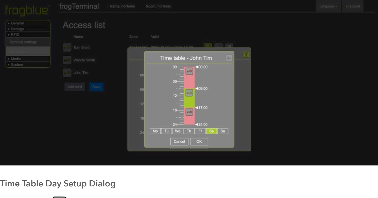
-
The
 button allows you to enable or disable access for specific sections of the timetable. For example, clicking the key buttons for Sa and Su will turn the sections for Saturday and Sunday red, indicating that access is now denied on weekends.
-
Clicking on a green or red day section of the timetable opens the
-
Time Table Day Setup Dialog for the selected day.
-
Day sections can also be dragged and dropped to copy time settings from one day to others.
-
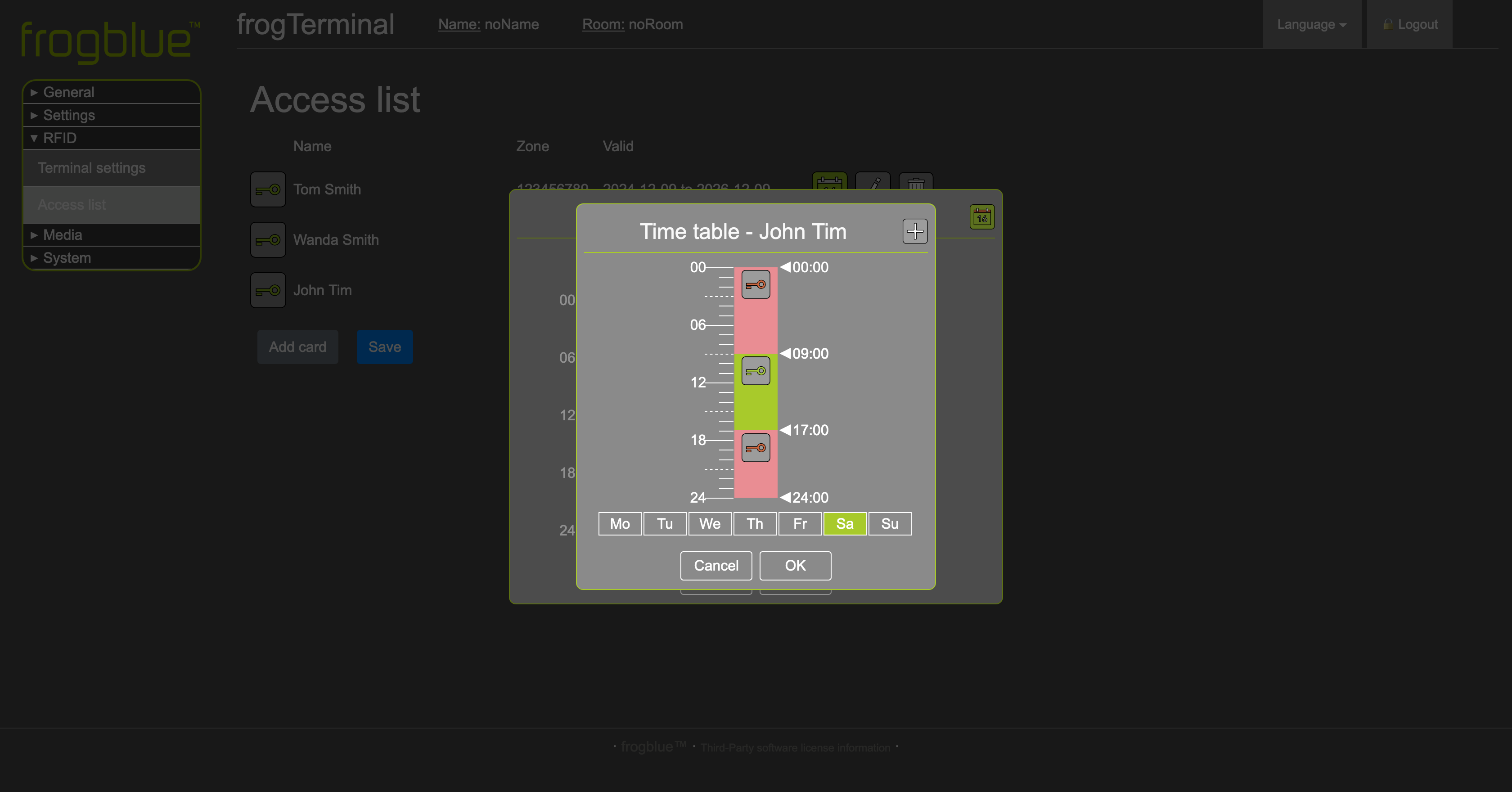
Time Table Day Setup Dialog
The
button toggles access for the relevant
time frame. A green icon indicates access is allowed, red indicates
access is denied.
The
 button opens the Time Table Day Dropdown
Dialog, enabling you to add additional time frames for more granular
control. For example, you can configure access to be denied after hours
but allowed from 9 a.m. to 5 p.m. during working hours.
button opens the Time Table Day Dropdown
Dialog, enabling you to add additional time frames for more granular
control. For example, you can configure access to be denied after hours
but allowed from 9 a.m. to 5 p.m. during working hours.
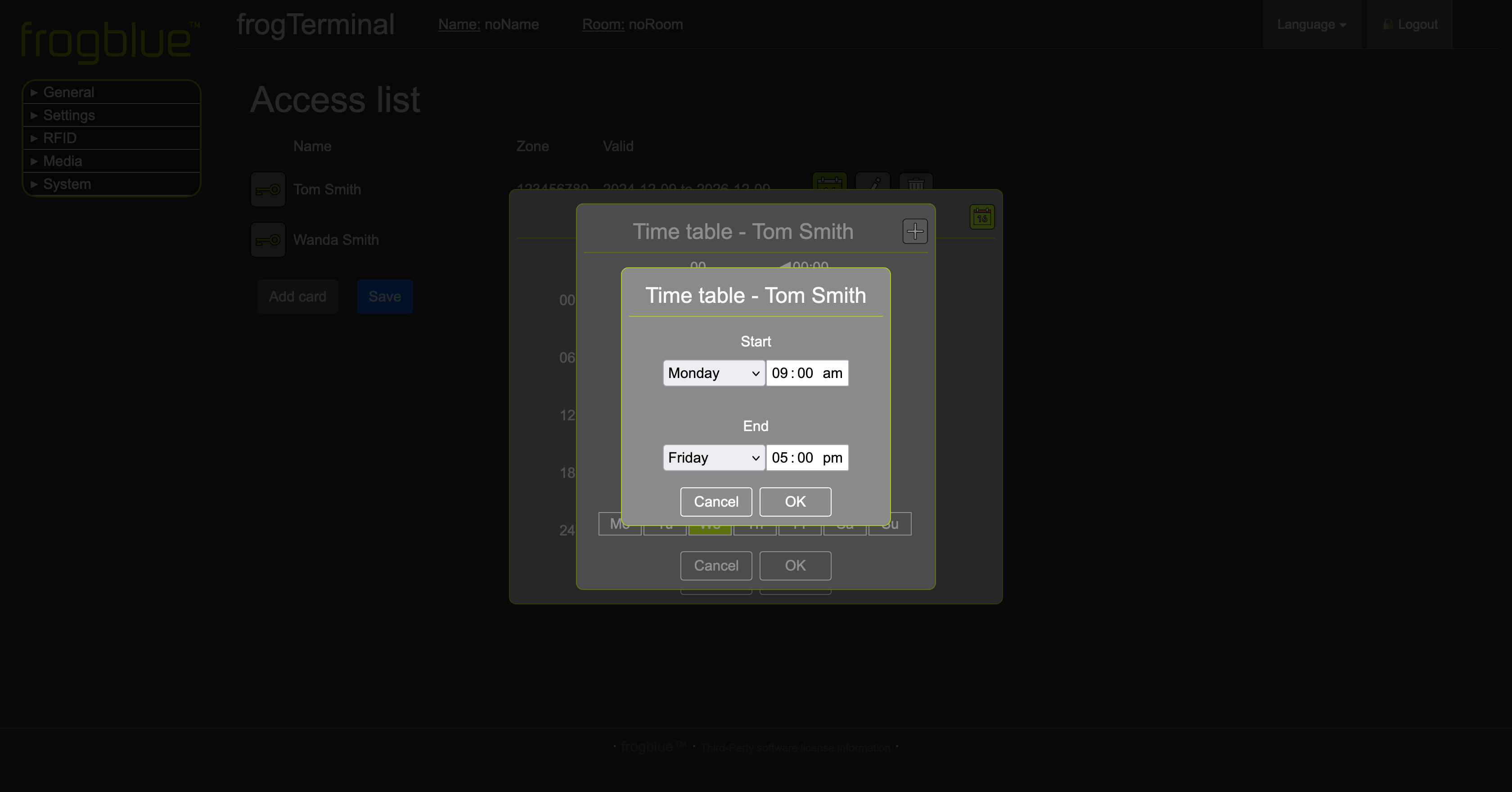
Time Table Day Dropdown Dialog
-
In this dialog, you can configure custom time frames for your timetable, such as 9 a.m. to 5 p.m.
- Time frames can also span multiple days, such as Monday to Friday, 9 a.m. to 5 p.m., providing flexibility for recurring schedules.
6.2. Special programs
Special programs define specific dates (i.e. public holidays) or date ranges (i.e. holidays) that can be referenced inside Time Profiles.
Name: e.g. Holidays
Date List: enter one item per line:
- Single day format: YYYY-MM-DD
- Date range format: YYYY-MM-DD..YYYY-MM-DD
Delete: bin icon removes the special program
Add new Special Program: + button (top right of the Special programs block)
Tip: Use Special programs for public holidays, shutdown periods, special events, etc.
6.3. Time Profiles
Time Profiles are the new mechanism (from frogOS 1.7 onwards) for defining time-based logic with multiple rules that can switch behaviour On or Off depending on the selected program and time window. The profiles are extremely flexible and fine-tuneable.
Name: e.g. TP_OpeningHours
Rules list (multiple rows), each row includes:
- Usage: On or Off
- Programs: e.g. Mon.-Fri., Sat.-Sun., or a Special program like Holidays
- From / Until: time window (hours + minutes)
- Remove rule: minus button on the right of the row
- Reorder: drag handle
 to change rule order.
 - Rules are resolved top to bottom.
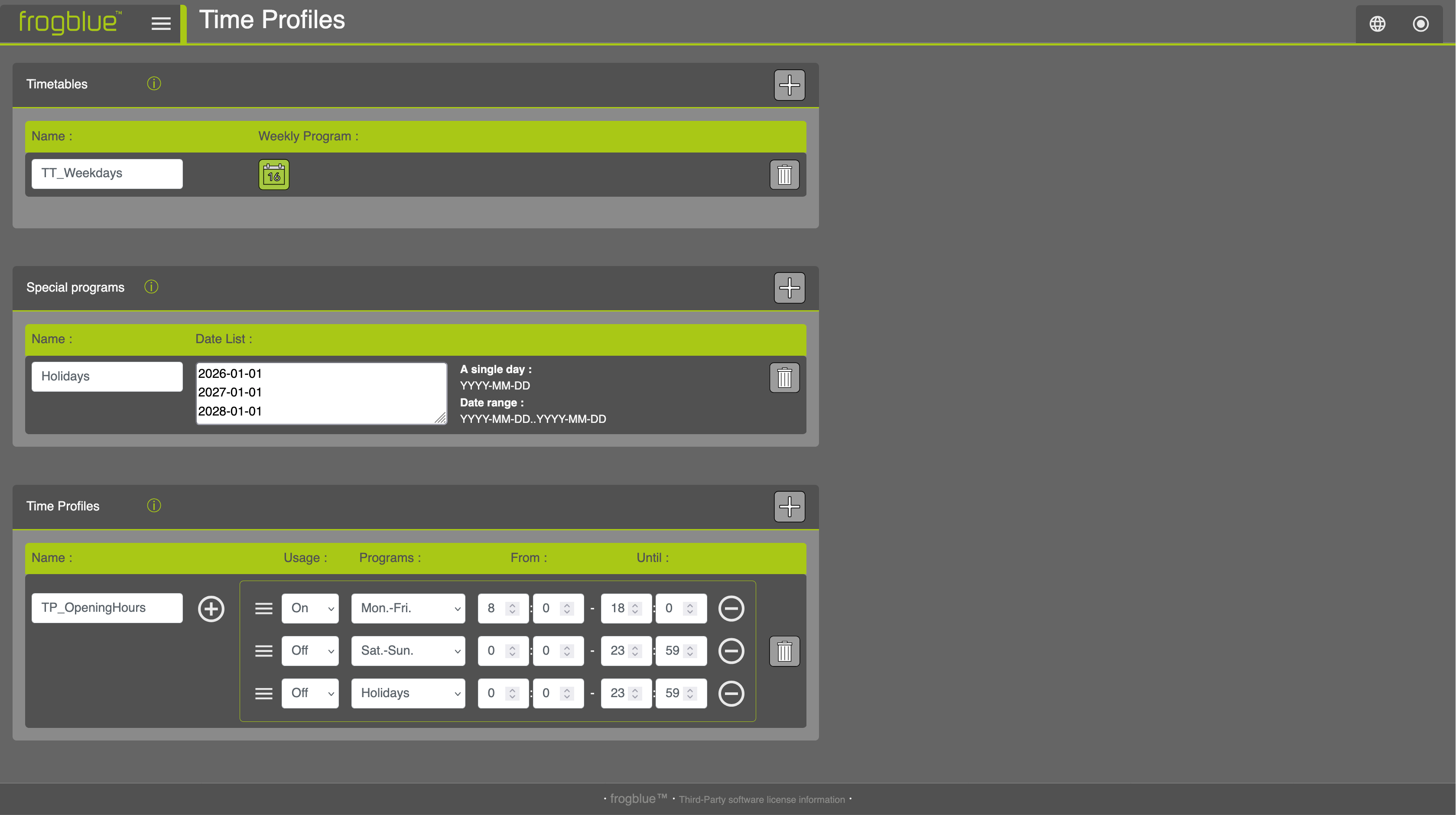
Delete profile: bin icon on the far right
Add rule/profile:
- + next to the profile name adds an additional rule row (as shown)
- + (top right of the Time Profiles block) creates a new Time Profile
The example shown in the screenshot above creates a clear “opening hours” logic where weekdays are active during business hours, and weekends/holidays are explicitly inactive.
7. Access Control Configuration
7.1. Introduction to frogTerminal Access Control
The frogTerminal offers efficient and flexible time-based access control using PINs, RFID cards, and even phone calls, without requiring a constant cloud or network connection. The system is designed to simplify access management while maintaining robust security.
For RFID cards, the frogTerminal employs the international standard DESFire EV2, ensuring reliability and security. Cards or key fobs can be written at any frogTerminal and then used across all terminals within the same project—no additional configuration is needed. While a network connection is optional, it enhances convenience by enabling remote administration via the network or internet.
7.2. PINs, Access Codes
There are a number of Numerical Codes for Operating the frogTerminal.
Admin Pin: A 6-digit numerical PIN used for administering the terminal configuration via the on-device touchscreen.
Function Pin: A numerical PIN ranging from 1 to 6 digits that can be mapped to any function on the frogTerminal. For example, “111” could be designated to call security.
Access Pin: A 6-digit numerical PIN associated with User Access Rules, granting access to doors or entry points as part of a two-factor authentication system that complements RFID cards or tags.
Note: Incorrect PIN entries will trigger a delay before the next PIN can be input. These delays increase incrementally (e.g., 5s, 10s, 20s, 30s, up to 60 seconds).
7.3. Graphical feedback for access events
| Step | Description |
|---|---|
| 1 | A successful access event. |
| 2 | A denied access event. |
| 3 | A denied access event. Reason: Card is not allowed access in this zone. |
| 4 | A denied access event. Reason: Time Table exception. Card is not allowed at this time. |
| 5 | A denied access event. Reason: PIN entered is invalid. |
| 6 | A denied access event. Reason: Card Issue date is invalid - card needs to be re-written/updated. |
| 7 | Multi factor PIN required for access. Reason: Card or Zone requires additional access PIN. Depending on source setting enter user’s PIN or Terminal Zone PIN codes. |
| 8 | The card is formatted incorrectly. |
| 9 | Project not written to card or wrong Project Number. |
7.4. Decentralised Access Control
With frogblue, user data is stored directly on the cards or key fobs, making the system highly independent of networks or clouds. Each frogTerminal reads the complete user data from the card when presented, ensuring seamless operation without external dependencies.
To enable secure access across all terminals in a project, encryption settings must be consistent. This requires entering the same 10-digit PIN and project date on each terminal. Updates to user data, such as PIN changes or modified access permissions, can be made at a single terminal (e.g., at the main entrance). The updated data is then automatically written to the user’s card during its next use. Card blocking is handled in the same way.
Future Enhancements: Upcoming updates will introduce the ability to manage user data remotely over the network or locally via Bluetooth. Additionally, a cloud-based access management system with time-tracking capabilities is planned.
7.5. Card Information
Each card securely stores essential user access details, including:
User’s name, first name, and personnel number
Card creation date
Validity period (start and end date/time)
Personal PIN
Weekly access schedules
Access permissions for up to 9 zones
frogTerminals read and interpret the card’s data directly. Any changes, such as new PINs or access schedules, are detected and seamlessly integrated during card usage. The terminal archives the card’s content and usage timestamp, enabling administrators to view user details and access logs on the terminal display. If a network connection is available, this data can also be accessed remotely via a web browser.
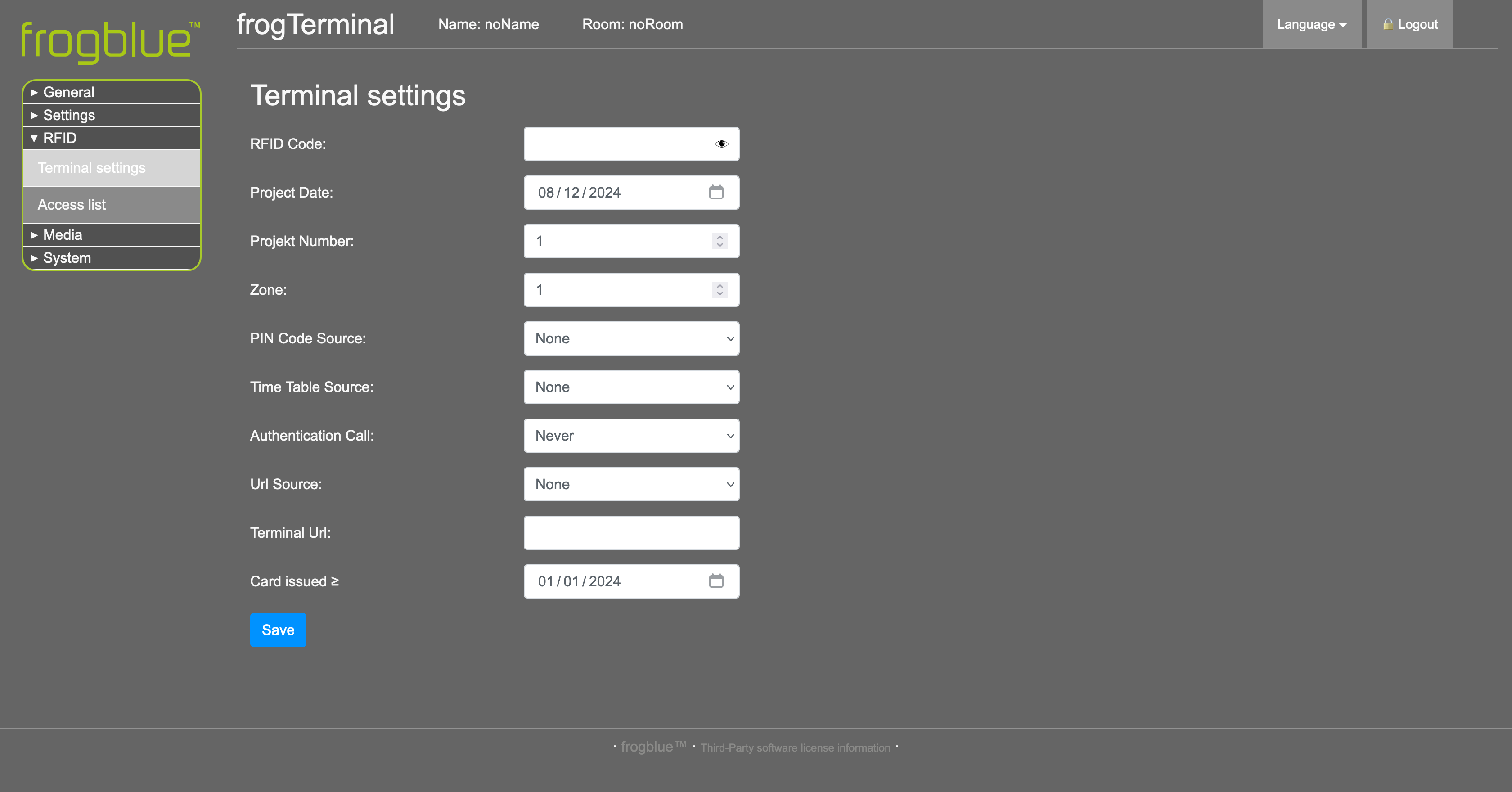
7.6. Access Functions
The card or key fob defines the user’s access rules, such as PINs, schedules, and authorised zones. The system also allows flexibility for special situations:
No PIN Requirement: For interior doors, the terminal can be set to bypass personal PIN validation (NONE).
Shared PIN: For temporary security needs, a terminal-specific PIN (TERMINAL) can be set, overriding the personal PINs for all users.
Access Times: Terminals can use access times stored on the card (CARD), set local schedules for all users (TERMINAL), or disable time restrictions entirely (NONE).
7.7. Special Features
frogTerminals support additional functionality to meet unique requirements:
Phone Integration: Cards can store a phone number, allowing the terminal to initiate a call after the card is read and authenticated.
IP Links: An IP link can be stored on the card, enabling automated actions such as triggering special functions or integrating with third-party systems like time tracking after authentication.
Advanced APIs: The frogTerminal API (application programming interface) provides for custom integrations making the terminal a powerful smart access control point and system interface for 3rd party solutions providers.
These features make frogTerminal a versatile solution for advanced access control and system integration.
7.8. RFID Encryption and Zones
Set up access control parameters like RFID encryption, zones, and project settings.
Steps Overview:
Configure RFID encryption (10-digit code, project date, and project number).
Assign the terminal to zones.
Set user-specific or terminal-wide PINs and schedules.
7.8.1. RFID Encryption and Zones Via Web Browser (Terminal Settings)
Via Web Browser Menu: Access Control → Terminal Settings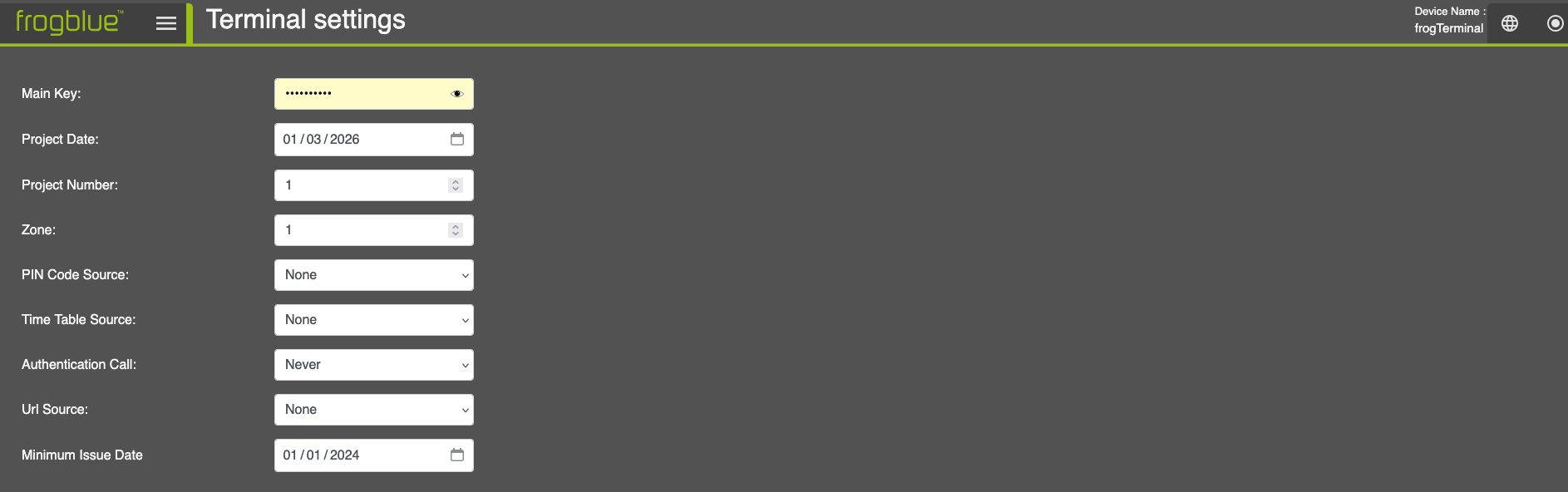
-
Main Key: 10-digit numerical code used with the Project Date and Project Number as the foundation (or “seed”) for encrypting your access control setup. Frogblue devices commissioned with the same code, date, and project number operate as a unified system.
-
Project Date: The timestamp used as a security seed, typically set to the last date on which this project was commissioned.
-
Project Number: A number between 1 and 32 767 used to identify the project, useful in managing multiple projects or complex setups.
-
Zone: A number from 1 to 9 that defines the access zone. The system supports up to 9 zones, each representing a specific access area (e.g., Carpark, Building A, Server Room, Security, etc.).
-
PIN code Source: Determines the source of stored PIN codes for two-factor authentication, with 3 options:
-
-
None: Disables PIN entry at this terminal.
-
Card: The most common setting, enabling two-factor authentication with specific PIN codes assigned to individual users and stored on the access card.
-
Terminal: Secures the door or access point with a terminal- specific PIN code. This PIN applies to all users at this location, overriding personal PINs.
-
Selecting the Terminal option shows an additional input box enabling you to set a 6-digit PIN for access at this Terminal.
-
Time Table Source: Specifies the source for time-based access rules, with 3 options:
-
None: Disables time-based access rules at this terminal.
-
Card: Time rules are stored on the access card, allowing individual schedules (e.g., General Staff: 9 a.m.–5 p.m., Cleaners: Fri-Sat 3 p.m.–7 p.m., Security: 24h).
-
Terminal: With this setting a door or access point may also be secured with a terminal-specific Time Table. Access times at this location are exactly as set locally in the Terminal.
-
Selecting the Terminal option shows an additional button for configuring the Terminal specific Time Tables. See Section 6.9 „Adding and Blocking Cards" on configuring Time Tables.
- Authentication Call:
This setting determines whether the terminal should initiate an authentication phone call to confirm access, such as verifying delivery access with dispatch, coordinating a contractor’s entry with site management, or enforcing the four-eyes principle for security.
There are 4 configuration options:
I. Never: Disables authentication calls for all access events at this terminal.
II. Card Value: The call settings (whether to call and whom to call) > are defined and stored on the access card, allowing individualised configurations for users.
III. Only Exception: Calls are made only for exceptional cases, such as access attempts outside defined time schedules or after incorrect PIN entries.
IV. Always: An authentication call is initiated for every access event, regardless of time schedules or PIN correctness, ensuring maximum oversight.
- URL Source: This setting determines whether the terminal should trigger an IP call or invoke a third-party API during access events. This feature enables integration with external systems, such as triggering special functions, logging access events, or interacting with third-party applications.
Examples include:Logistics: Notify warehouse automation systems to prepare or dispatch an order upon access. Automatically light a path to the delivery gate for efficient navigation.
Healthcare: Trigger nurse call or management systems to log patient visitor details or confirm the delivery of critical medication.
Building Automation: Activate lighting and adjust HVAC settings along a defined route for the user, or automatically call an elevator to the correct floor.
Workforce Management: Log staff check-in/check-out times for attendance tracking or initiate a workflow when a technician accesses a specific area.
Security and Monitoring: Notify a security team or system when a restricted zone is accessed, or log entries for audit purposes.
There are 3 configuration options:
I. None: Disables URL triggering for access events at this terminal.
II. Card: The URL to be triggered is defined and stored on the access card, allowing customised actions for individual users.
III. Terminal: A specific URL is set locally on the terminal and triggered universally for all access events at this location. > This setting is ideal for standardised integrations across multiple users. Selecting the Terminal option shows an additional input box Terminal URL. This URL triggers, when the URL Source setting is configured as Terminal. It allows the terminal to initiate standardised API calls or IP actions for all access events.
- Minimum Issue Date: Specifies the earliest creation date for cards allowed access at this terminal. Cards issued before this date are automatically denied.
This setting provides for a simple security measure in case of a potential breach (e.g., lost access keys) just set this date to the current day, all older cards are immediately blocked, all personnel must now present their keys for re-writing with updated credentials.
- The
 button saves the updated access settings to the terminal.
7.8.2. RFID Encryption and Zones Via On-Device Touch Screen
| Step | Description |
|---|---|
| 1 | Tap the settings icon and enter your 6-digit Admin PIN to access the configuration mode. |
| 2 | Tap the RFID icon to access the RFID Terminal settings page. |
| 3 | The settings on this page are identical to the settings in the Browser detailed in section 6.8.1 “RFID Encryption and Zones Via Web Browser”. |
7.9. Formatting Keys /Cards via On-Device Touch Screen
| Step | Description |
|---|---|
| 1 | Tap the settings icon and enter your 6-digit Admin PIN to access the configuration mode. |
| 2 | Tap the RFID icon to access the RFID key settings page. |
| 3 | Hold your RFID card or tag in front of the Terminal’s RFID sensor. |
| 4 | Hold the key/card at the Terminal’s RFID sensor, wait for the beep confirmation sound and your card has been formatted to defaults. |
| 5 | Tap the info icon to open the RFID Card info dialog. |
| 6 | Confirm you wish to completely erase all data on the card. |
| 7 | This screen shows the Projects or Applications stored on the card or key. Select a project and tap Delete then confirm and hold the key/card in front of the Terminal to erase the project. To format the entire card, use the Format option. |
Be sure to always format your cards before re-writing.
7.10. Adding and Blocking Cards
How to add RFID cards or key tags for user access and manage blocking when necessary.
Steps Overview:
Add a card via touch screen or web interface.
Assign access zones and schedules.
Block a card.
7.10.1. Adding and Blocking Cards Via Web Browser
Menu: Access Control → Access Rules
Access List
-
This section displays the access list, detailing the personnel whose access data is stored on this terminal.
-
The
button toggles master access for this user. A green icon indicates access is allowed, while a red icon indicates it is denied. -
The
 button opens the timetable configuration for the user. Refer to the Time Profil Section.
Note: To be able to use the TimeProfiles make sure to set the Timetable Source at the Terminal Settings to either Card or Terminal (see Section 7.8.1: RFID Encryption and Zones Via Web Browser (Terminal Settings))
button opens the timetable configuration for the user. Refer to the Time Profil Section.
Note: To be able to use the TimeProfiles make sure to set the Timetable Source at the Terminal Settings to either Card or Terminal (see Section 7.8.1: RFID Encryption and Zones Via Web Browser (Terminal Settings))
-
-
The
 button opens the Edit Card
-
Dialog. This dialog mirrors the Add Card Dialog settings, except it edits the configuration for the selected entry.
-
Information on the Add Card Dialog can be found below.
-
The
 button deletes the user’s access configuration entry from this terminal.
Note: This does not block the card from accessing the system. It only clears the cached personnel card data on this terminal. A card written with the correct encryption key can still authenticate and gain access if the source settings allow. In such cases, the card will ‘carry’
button deletes the user’s access configuration entry from this terminal.
Note: This does not block the card from accessing the system. It only clears the cached personnel card data on this terminal. A card written with the correct encryption key can still authenticate and gain access if the source settings allow. In such cases, the card will ‘carry’ -
the data to the terminal, creating or updating an entry in the access list with the card’s details.
-
-
The
 button allows you to manually add a new personnel card entry to the system.
- The button saves the updated access settings to the terminal.
- The
Note: For systems with multiple terminals, new or updated access information is distributed either decentralised via the card when presented to a terminal during the next access event, or in real-time via frogCast (Unified Bluetooth/IP Mesh) across the IP network.
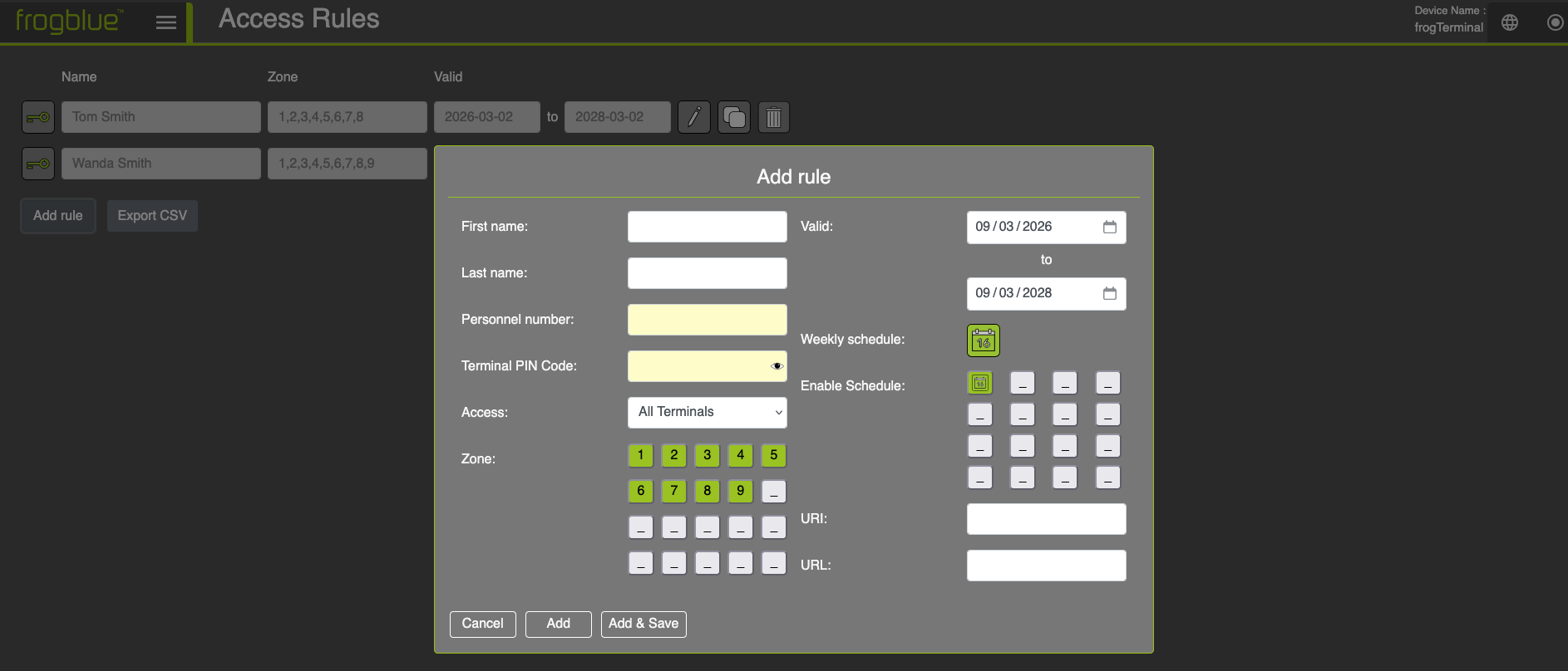
Add Card Dialog
-
First name: The given name of the person associated with this card.
-
Last name: The surname of the person associated with this card.
-
Personnel number: A unique number or identifier for the person associated with this card.
-
Terminal PIN Code: The unique access PIN code for the person associated with this card. This code is required when Terminal Settings - > PIN Code Source is set to Card.
-
Access: Specifies whether this entry applies only to this terminal or to all terminals in the project.
-
Zone: Specifies the zones this card grants access to. Clicking on the numbers
 through
  toggles wether access is allowed or denied for each zone. For example, selecting
  grants access only to zones 3, 6, and 9.
 -
Valid: The date range during which this access entry is valid.
-
Weekly schedule: A time table as explained in Section 6.1 Time Tables opens and can be edited.
-
Enable schedule: Enable/disable the time table set in Weekly schedule and up to 15 time profiles. For details see Section 6.3 Time Profiles. As for Zone clicking on the number toggles wether the time profile is active or not.
-
URI: The URL triggered in case of an exception, such as an access denied event.
-
URL: The URL triggered on successful access.
-
7.10.2. Adding and Blocking Keys / Cards Via On-Device Touch Screen
| Step | Description |
|---|---|
| 1 | Tap the settings icon and enter your 6-digit Admin PIN to access the configuration mode. |
| 2 | Tap the access rules icon to access the access rules settings page. |
| 3 | Tap the add icon to add an access rule entry. Note: The add card dialog is identical with the Edit Card dialog. |
| 4 | Active: Enable or disable this card for access across the project. When set to off, this card will be automatically blocked when presented to a Terminal. RFID Card necessary: Defines if an RFID card is required for this access rule. |
| 5 | Zone: Specifies the zones this card allows access to. Clicking on the numbers 1 through 9 toggles whether access is allowed or denied for each zone. Validity: The date range during which this access entry is valid. |
| 6 | Hold the card at the Terminal’s RFID sensor and wait for the beep confirmation sound. |
8. Telephony Call Destinations Setup
8.1. Bell Signs
Via Web Browser Menu: Settings → Call destinations
Here we set up the Bell Signs, which appear on the Terminals touch screen when activated e.g. by touch or the proximity sensor.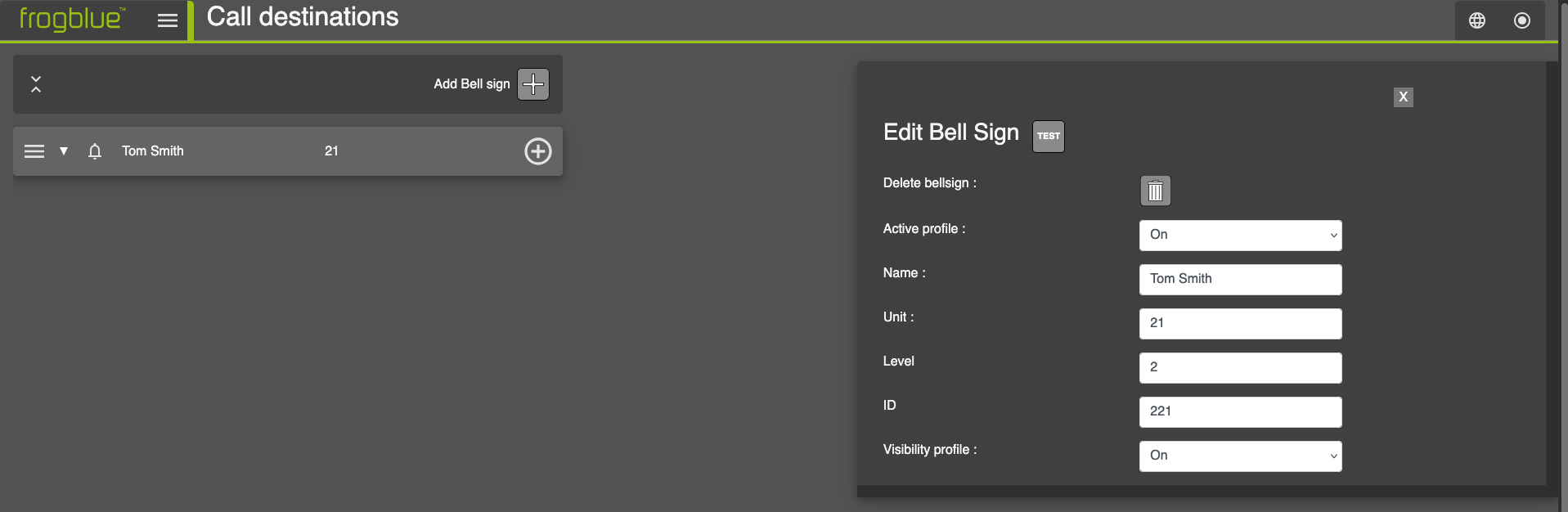
-
Click Add Bell Sign to create a new bell sign. A new entry will appear in the bell signs list.
-
 Adjust the position of the entry in the list and set the default order in which the buttons appear on the terminal’s touchscreen.
-
 Deletes the bell sign entry.
 -
Active profile: Enabling the entry makes it visible on the touchscreen and available as a call target. Disabling it removes it from the touchscreen and prevents it from being used as a call target.
-
-
Name: The display name for the entry on the touchscreen call button (i.e., ‘Tom Smith’).
-
Unit (Optional): Specifies the Apartment or Unit number (i.e.
-
‘21’).
-
Level (Optional): The floor level for the entry (i.e. ‘2’).
-
ID (Optional): An identifier for this entry (e.g., ‘221’ could represent level 2, unit 21).
-
-
Visibility profile: Choose whether to hide or show this entry on the terminal’s touchscreen display. Hidden entries can still function as call targets programmatically (e.g., via APIs) or for authentication calls.
-
Actions and Users: Defines the actions triggered when a bell button is tapped or activated. Use the
 button to add a new action entry.
- The numbers shown indicate the current selection and the total number of actions for this bell sign entry (current/total).
Bell actions can be stacked using various parameters—such as time tables and delays—to execute different actions at designated times or in sequence.
Hitting the
button opens a dialog where we can
choose from a number of Action types using the drop down menu:
8.1.1. Bell Actions: Invite frogSIP user
Here you can pair your Terminal with smartphones running the frogSIP App.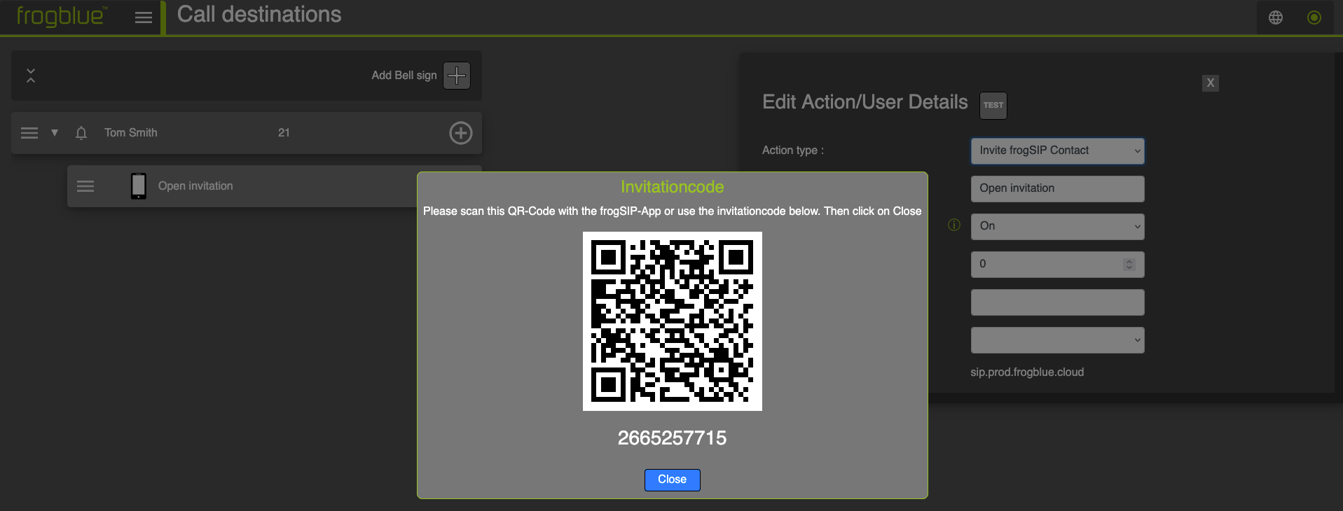
Select Invite frogSIP Contact from the drop-down menu
Scan the QR code or the enter invite code in the frogSIP App. See section 5.6 Pairing the Terminal with frogSIP App
8.1.2. Bell Actions: Call frogCloud SIP Account
Bell Actions: Call SIP device by IP via SIP Server
For directly calling SIP telephony devices via IP
Select Call SIP Device by IP from the drop-down menu.
Name: Enter a name for the action e.g. ‘IP-Phone-Unit-21**’**.
Active profile: Select a time profile in which the bell sign is active.
Delay: Time in seconds until call action is executed.
Incoming call handling: You can directly decline, accept the call manually or answer by audio and/or video.
Direct call IP address: The IP Address of the SIP phone device to call.
Click Save to create a new SIP call by IP action.
When installed with a SIP server, calls can be made to any phone on the system. The SIP server must be configured first - see Section 17.2. „SIP Server Registration", for details.
8.1.4. Bell Actions: Use Custom SIP Server
8.1.5. Bell Actions: Send frogMessage
This feature enables seamless integration with frogblue’s smart automation mesh, allowing for automated control of lights, doors, and shutters. It requires provisioning your frogTerminal for frogMesh integration – see Section 16.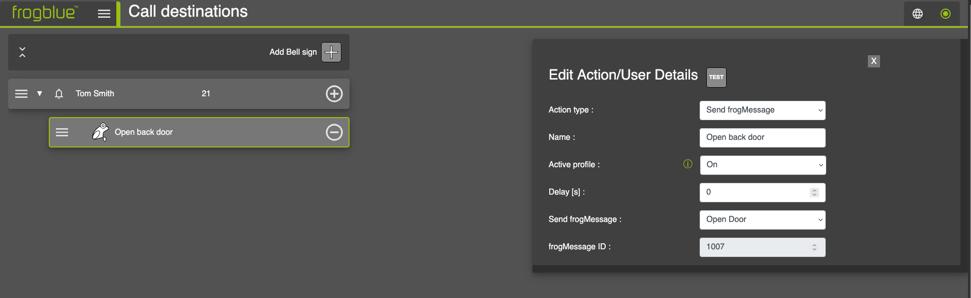
-
Action type: Select Send frogMessage from the drop-down menu.
-
Name: Enter a name for the action e.g. ‘Open back door’.
-
Active profile: Select a time profile in which the bell sign is active.
-
Delay: Time in seconds until the frogMessage is executed.
-
Send frogMessage: Select the frogMessage you wish to send from the drop-down menu.
-
frogMessage ID: Unique number to identify the frogMessage. The ID is automatically assigned to each frogMessage once a frogMessage is created.
-
8.1.6. Bell Actions: Activate Built-in-Relay
This feature enables you to directly trigger the frogTerminal’s built-in hardware relay. For example, a bell button can be configured to activate an external light or another system via the relay.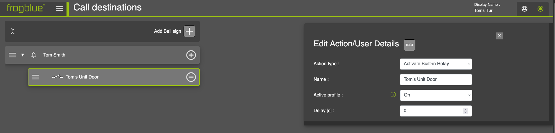
-
Action type: Select Activate Built-in Relay from the drop-down menu.
-
Name: Enter a name for the action i.e. Tom’s Unit Door.
-
Active profile: Select a time profile in which the bell sign is active.
-
Delay: Time in seconds until the relay is triggered.
-
Bell Actions: Start opener sequence
This feature allows you to trigger predefined opener sequences or home objects, offering advanced control over multiple entry points. For example, you can configure the system to open a gate and then, after a set delay (e.g., 20 seconds), automatically open a garage door. This functionality enhances automation by streamlining sequential access events.
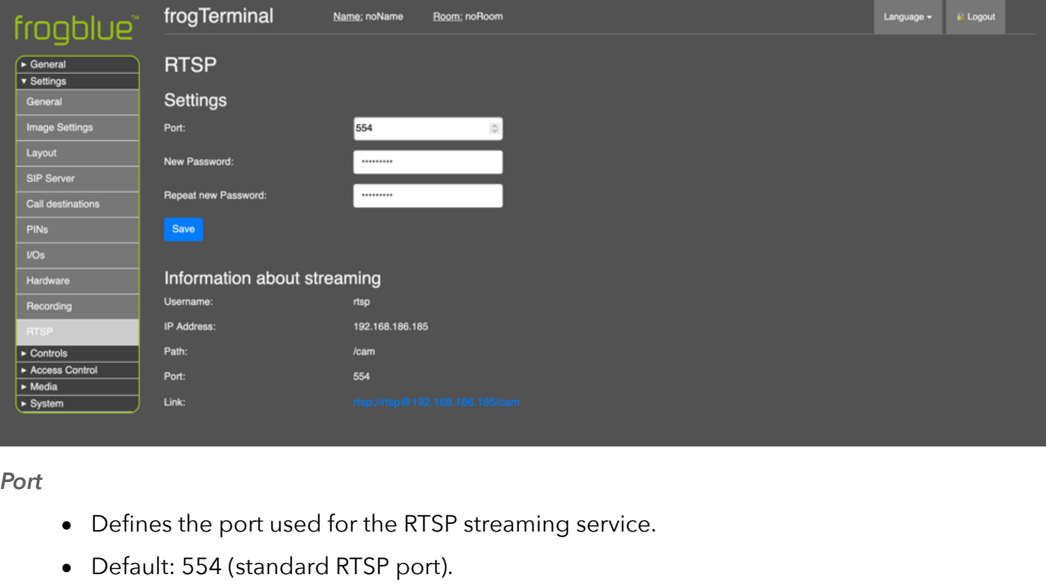
-
Action or user: Select Start opener sequence from the drop-down menu.
-
Action name: Enter a name for the action i.e. Tom’s Front Door.
-
frogMessage: The IP Address of the SIP phone device to call.
-
8.1.9. Bell Actions: Send IP-Notify
This feature enables seamless integration with third-party IP devices, allowing a bell button to send network notifications that can trigger external systems such as an IP gate opener.
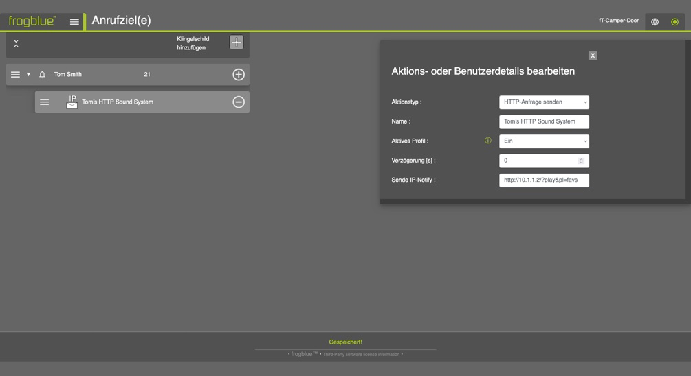
-
Action or user: Select Send IP-Notify from the drop-down menu.
-
Action name: Enter a name for the action i.e. Tom’s Front Gate.
-
URL: The URL to trigger o this action where the IP Address is that of your Gate Opener device, 8080 the port, and /control/open the command it expects to open the gate.
-
8.1.10. Bell Actions: Show image or clip
This feature displays a preloaded image, such as a company logo, on the terminal’s screen when the bell button is pressed, enhancing brand visibility or providing a clear visual cue for users.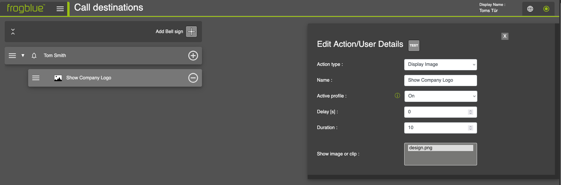
-
Action type: Select Display Image from the drop-down menu.
-
Name: Enter a name for the action i.e. Show Company Logo.
-
Active profile: Select a time profile in which the bell sign is active.
-
Delay: Time in seconds until the file is displayed.
-
Duration: Time in seconds, how long the file is displayed.
-
Show image or clip: Select a file that was previously uploaded to the terminal under Media on the terminal’s web interface.
-
For further details, please refer to Section 15: „On-board Media Settings".
-
8.1.11. Bell Actions: Next Call Action
This function defines which item should be called next after an action. It provides a simple way to set up redirects.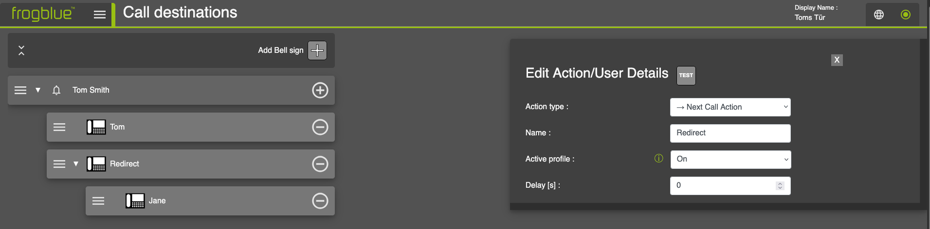
-
Action type: Select Next Call Action from the drop-down menu.
-
Name: Enter a name for the action i.e. Redirect.
-
Active profile: Select a time profile in which the redirect is active.
-
Delay: Time in seconds until the redirect is called.
-
In this example, Tom is called first. If he does not respond or declines the call, it is automatically forwarded to Jane. To add the Janes bell action, click on the „+"-Symbol right next to Tom Smith as usual.
8.1.12. Bell Actions: Notify MOBOTIX MxMC
8.1.13. Bell Actions: Sound Action
The Terminal plays a pre-defined sound as soon as the bell button is pressed. This functionality is especially useful for testing purposes.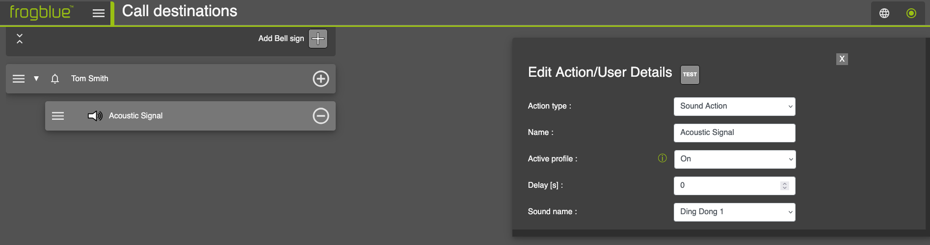
-
Action type: Select Sound Action from the drop-down menu.
-
Name: Enter a name for the action e.g. Acoustic Signal.
-
Active profile: Select a time profile in which the sound is active.
-
Delay: Time in seconds until the sound is played.
-
Sound name: Choose a pre-defined sound from the dropdown menu.
-
Alternatively, use your own audio files, which needs to be imported at Medien → Audiodateien in advance.
-
8.2. Authentication Call Target
Via Web Browser Menu: Settings → Call-related actions
Configure the target for multi-factor authentication calls. This call is initiated during an Access Event when the Authentication Call is triggered based on the defined Access Rule.
8.3. Auto actions
Via Web Browser Menu: Settings → Call-related actions
Define the call targets for events or errors at the Terminal:
Preview call: Initiated when the proximity or motion sensors are triggered for the specified Delay period and no action is taken e.g., a loitering event.
Touch call: Initiated when the touch screen is activated for the specified Delay period without any valid function being executed e.g., suspected tampering.
Invalid call: Initiated when the number of errors exceeds the configured threshold e.g., three consecutive incorrect PIN entries or an unrecognised card / key scan.
9. Event Management
Via Web Browser Menu: Settings → Event management
The Event Management section is used to configure event-based behaviour within the system. Here you define:
Events or Triggers (what happens)
Conditions (under which circumstances)
Actions or action chains (what the system should do)
This allows you to implement customised automation logic such as:
-
When a specific frogMessage is received (Event) from 10:00 AM (Condition) → play a sound and send an IP message (Action).
-
When an external system sends an IP message containing „OpenDoor"
-
(Event) → trigger a HomeObject or local output relay (Action).
-
When a SIP call is received (Event) → trigger a light output (Action).
-
Adding a New Event
-
Select the Event Type from the drop-down menu and click the “+”
button.
-
A configuration dialog opens where you can edit the event parameters.
-
Save the event.
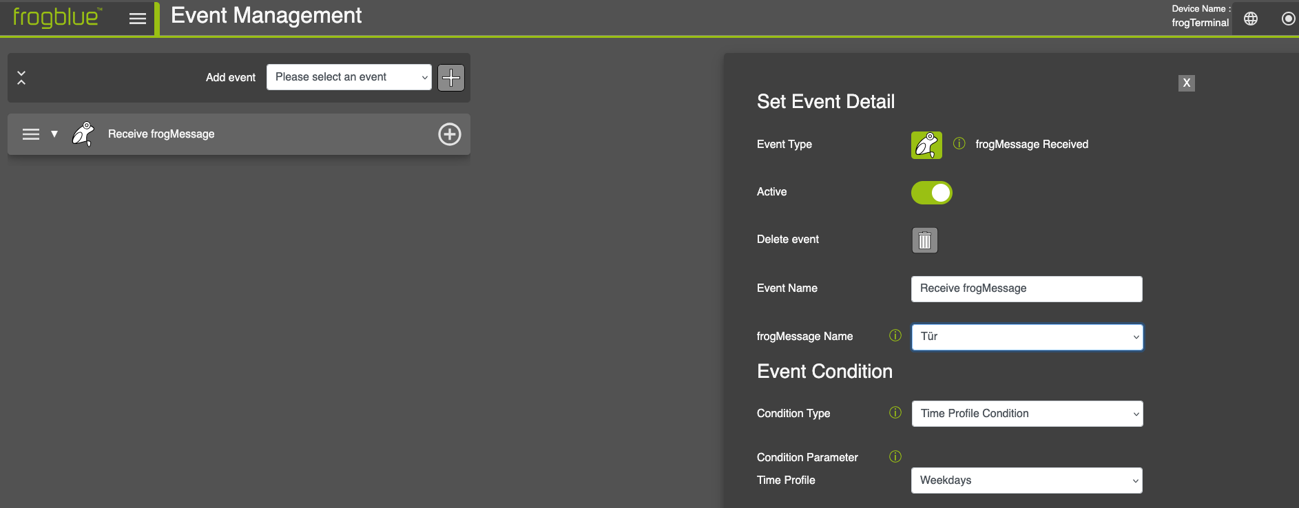
The configuration dialog follows a similar structure for all event types:
-
Active: Activate or de-activate the event.
-
Delete event: Completely remove this event configuration with associated action(s).
-
Event Name: Assign a meaningful name for easier identification.
-
Event Parameter: The parameter field changes depending on the selected event type. Examples are:
- Port: <Port to Listen for IP Message Event>
-
frogMessage Name
-
IP Notify String
-
Timer Interval
-
Local Variable
-
Condition Type: Condition Types define when the event should execute its actions.
-
- No Condition: The actions are always triggered when the event occurs.
-
-
Regex Condition: Triggers only if the received value matches a regular expression pattern.
-
Value Equal Condition: Triggers only if the received value exactly matches the defined String
-
Time Table Condition: Triggers only during a specific timetable (calendar-based schedule).
-
Time Profile Condition: Triggers based on a predefined time profile.
-
Variable Equal Condition: Triggers when a defined variable matches a specified value. Variable are define with a $ i.e. $myVar1
-
Compare Condition: Triggers when a comparison rule is met (e.g.
-
$myVar1greater than, less than, equal to $value)
-
Note that in the example above, only event (the frogMessage door is
received) and condition (time profile: Weekdays) have been defined. So
far, no action has been executed. The desired action can be added by
clicking the “+” symbol next to the event
name.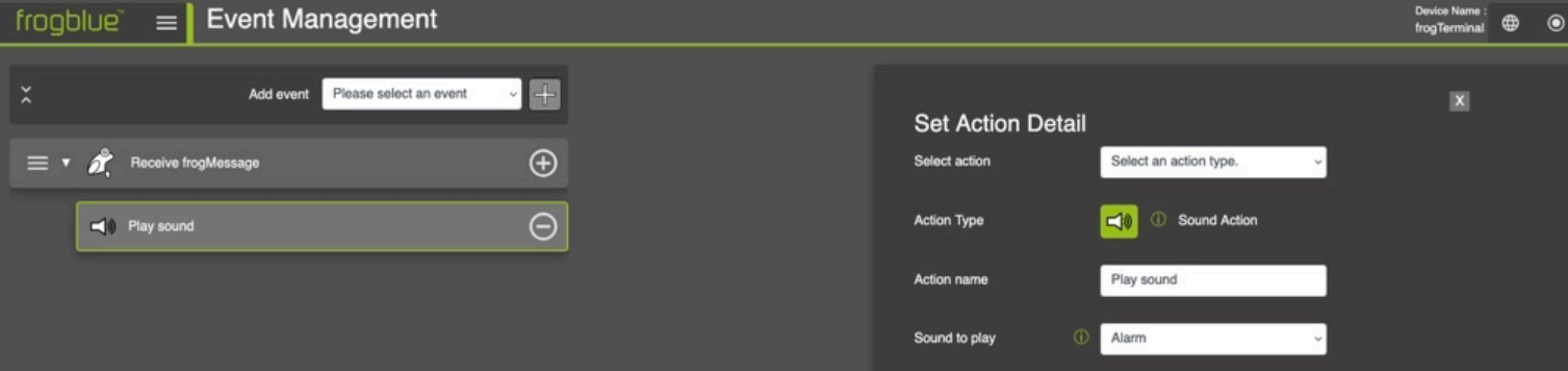
Set Action Detail
-
Select action: Choose one action.
-
Action Typ: The selected action
-
Action name: Assign a meaningful name to your action.
-
Depending on the selected action, different configuration options for that action will appear after the action name.
-
Now, a sound is played (Action) as soon as the frogMessage Door is received (Event) on weekdays (Condition).
9.1. Events
We differentiate between the following events:
9.1.1. frogMessage Received
This event is triggered, when a frogMessage is received. The Event Parameter changes to frogMessage Name.
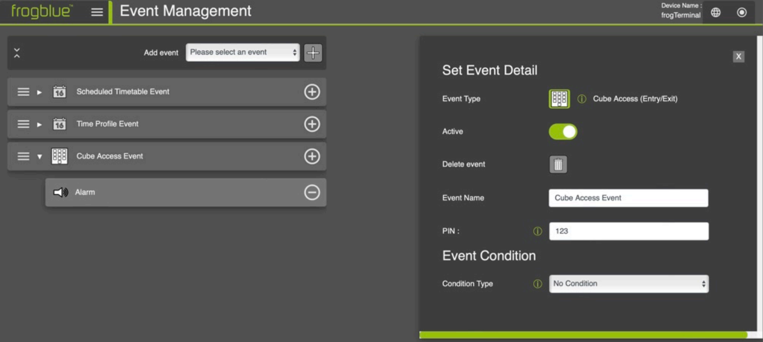
- frogMessage Name: Name of the frogMessage
Cube Access
The event is initiated, when a cubeAccess PIN has been sent.
Before this event can be configured, the cubeAccess must be integrated into a project using the frogProject app. Do not make any changes to the configuration of the cubeAccess, and write the initial configuration to cubeAccess and frogTerminal.
- PIN: Enter a function PIN that uses CubeAccess as its PIN source.
9.1.3. IP Notify Event
The event checks for new IP-Notify
messages.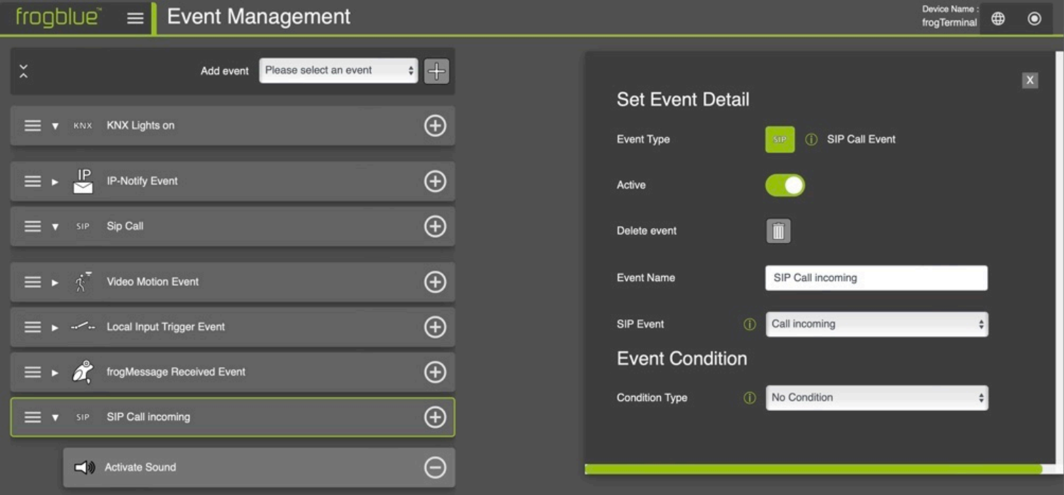
- Port: By default, the port set under System → Network is used.
- Alternatively, you can set your own port.
9.1.4. KNX System Event
A KNX address was sent.
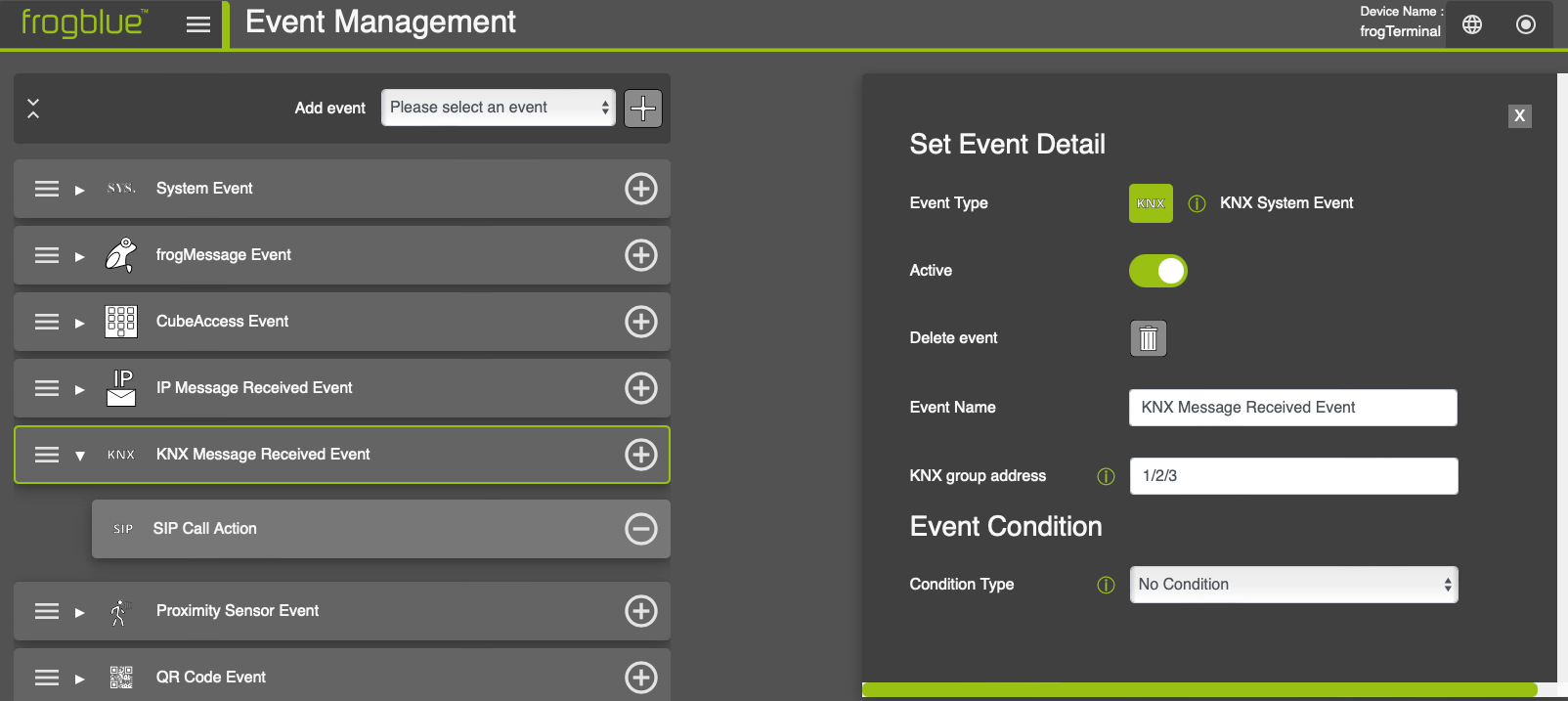
- KNX group address: Enter a KNX Group Address. Example:
- Main/Middle/Sub → 1/2/3
9.1.5. Local Input Trigger
This event occurs, when an input event at the local input port is detected.
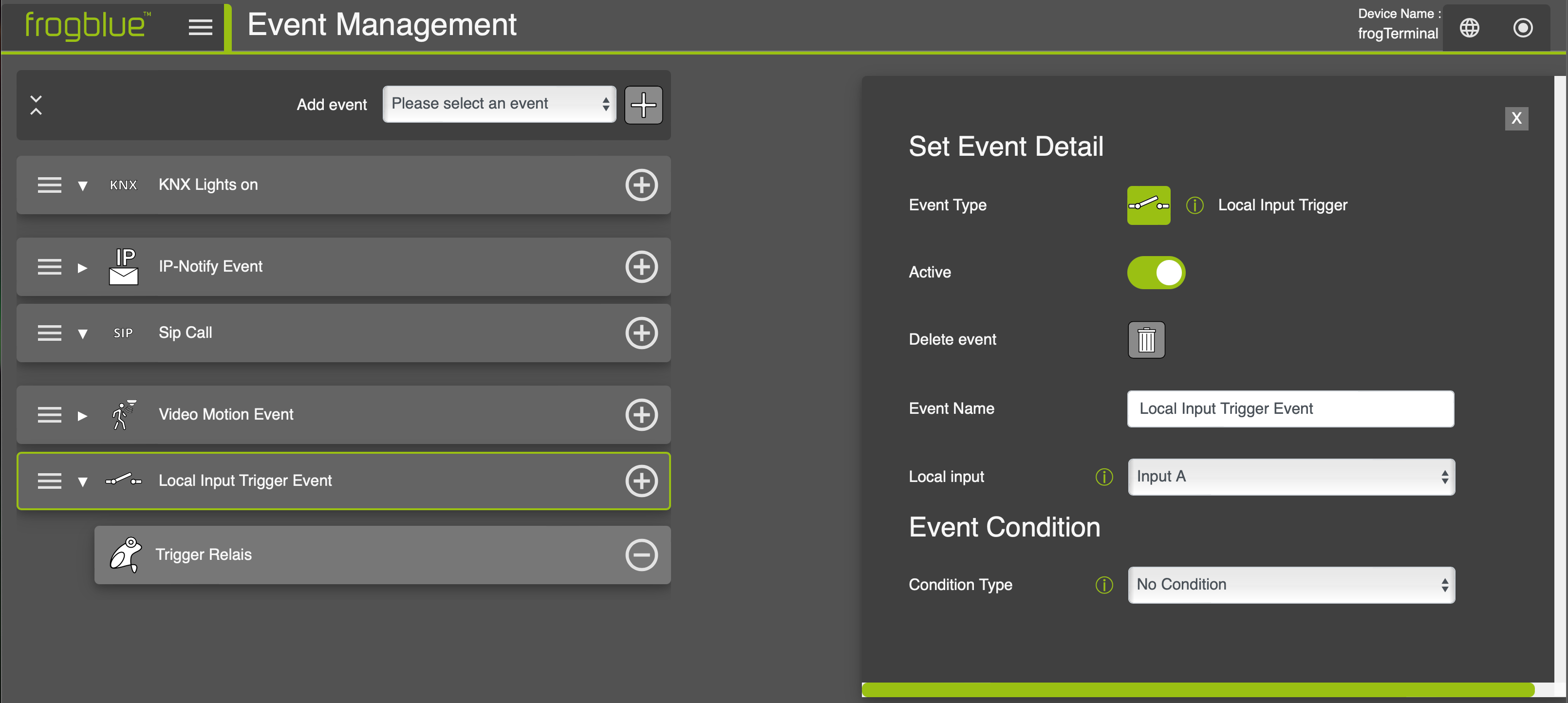
- Local Input: Choose local input A or B
9.1.6. SIP Call Event
An incoming SIP call
For SIP Event choose one of the following SIP Event types: The event is triggered as soon as
-
Call incoming: an incoming call is registered.
-
Call outgoing: an outgoing call is registered.
-
Call closed: a call is closed.
-
Call DTMF start:
-
Call denied: a call is denied.
-
Maximum ring duration reached: the maximum ring duration set under Settings → General is reached*.*
-
Maximum call duration reached: the maximum call duration set under Settings → General is reached*.*
-
Ringing: the device is still ringing.
-
Call answered: the call is answered.
-
Call established: the call is established.
-
9.1.7. Proximity Trigger
Event when the proximity sensor detects the presence of an object
- Sensor threshold: Enter the desired sensitivity threshold for the proximity sensor. A higher value results in a shorter detection range.
9.1.8. Interval Time Event
Event occurrence after timeout
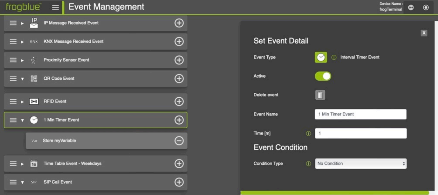
- Time: Enter the time in minutes after which the event will be triggered repeatedly.
9.1.9. Time Profile Event
The event occurs at the times defined in the time profile.
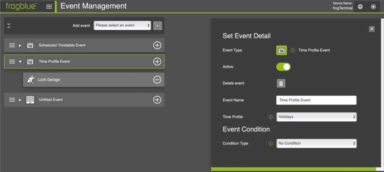
- Time Profile: Include a time profile that you previously created under Settings → Time profiles.
9.2. Actions
After defining the event, you can choose between the following actions:
9.2.1. FrogMessage Action
Triggers a
frogMessage.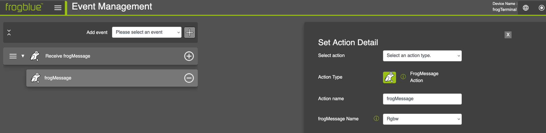
- frogMessage Name: Choose an existing frogMessage from the dropdown menu.
9.2.2. HomeObject Action
Triggers a
HomeObject.
- Homeobject to trigger: Select an existing HomeObject from the dropdown menu.
9.2.3. HTTP Action
Calls an http
address.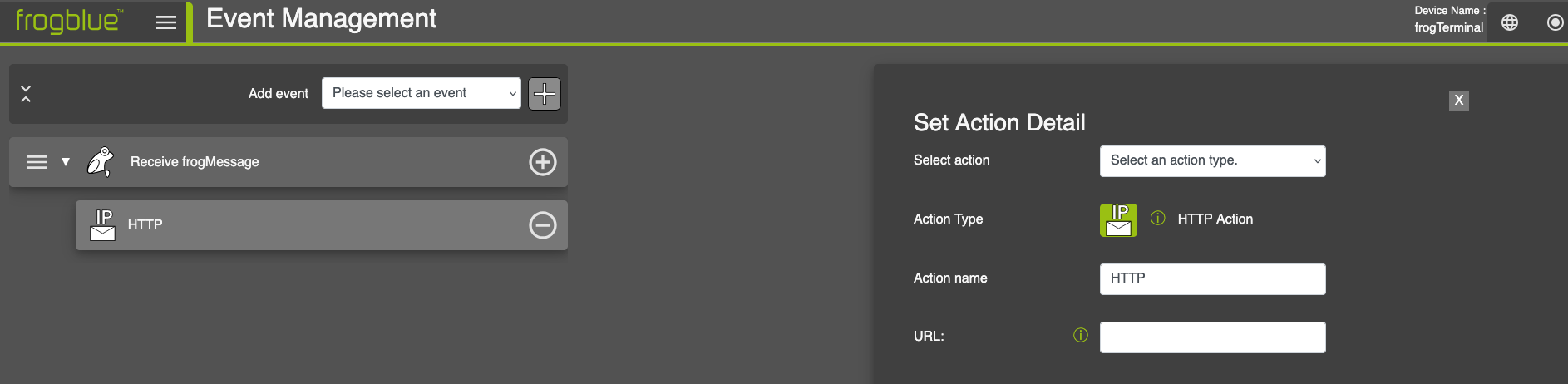
- URL: Provide a URL (http) for the web resource.
9.2.4. HTTP Post Camera Action
Triggers an http post that contains the current camera image in the
body.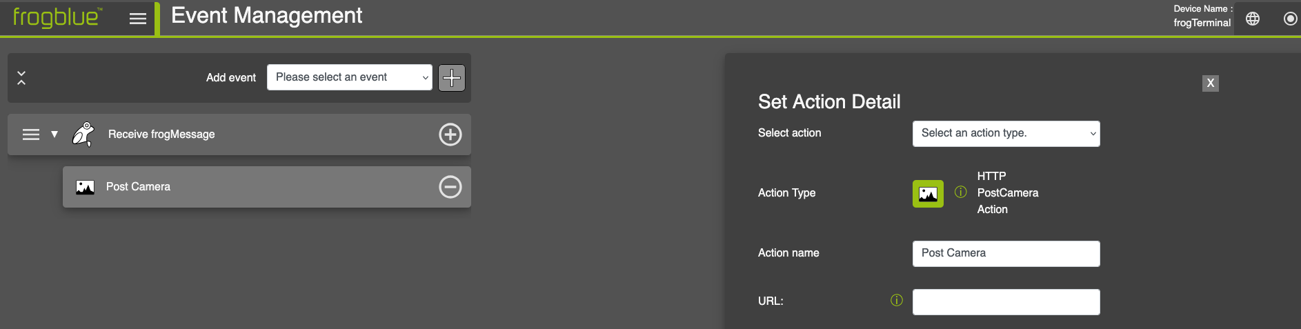
- URL: Enter a target URL.
9.2.5. IP-Notify Action
Sends an IP
Notify.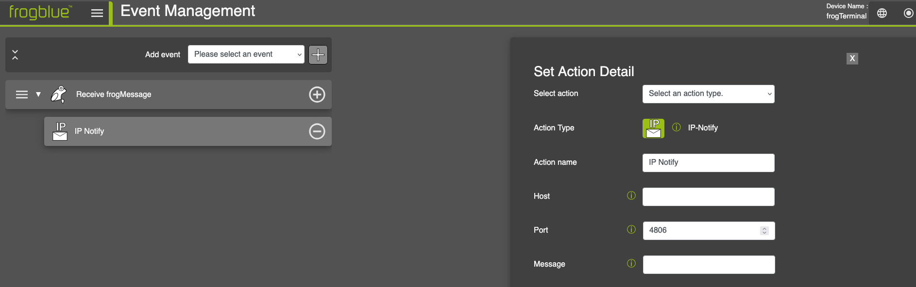
-
Host: Provide the destination host or IP address.
-
Port: Destination port. By default, the port set under System → Network is used.
-
Message: Define the message to be sent. Use $value as a placeholder for the event value.
-
9.2.6. KNX Action
Triggers a KNX
action.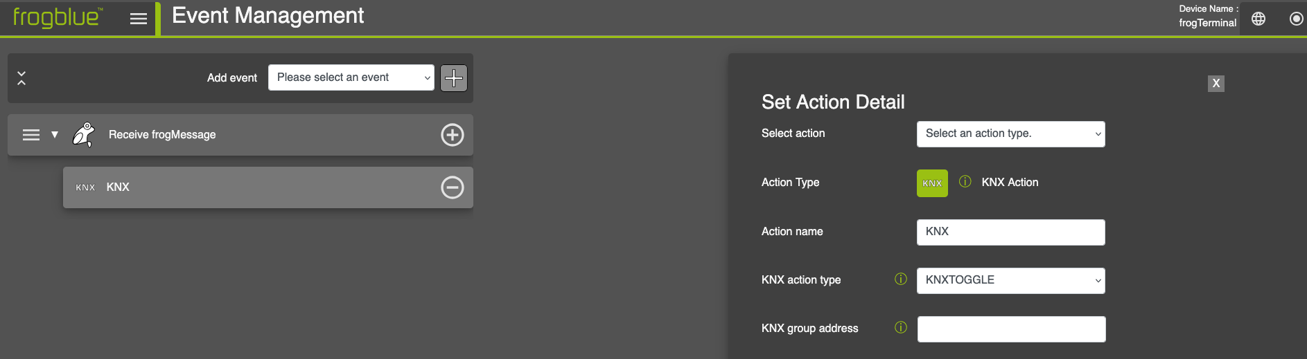
-
KNX action type: Select the type of KNX action. Choose between KNX Toggle and KNX SetValue.
- KNX group address: Enter a KNX group address. Example:
- Main/Middle/Sub → 1/2/3
9.2.7. Local Output Action
Triggers the frogTerminal’s local
output.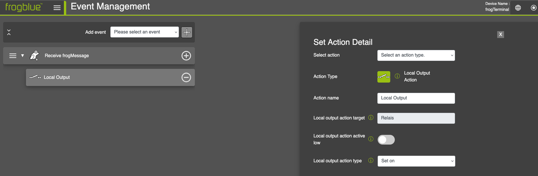
-
Local output action target: I
-
Local output action active low: I
-
Local output action type: I
-
-
-
- Set on: T
-
-
-
Set off: T
-
Toggle: T
-
Set on for time: Duration in milliseconds for which the local output stays active.
-
Set to event value: T
-
9.2.8. SIP Action
Starts a SIP
call.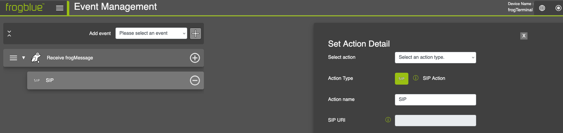
- SIP URI: Enter a SIP URI. Format: sip:user@host[:port].
- Example: sip:bob.smith@example.com or sip:1234@192.0.2.1:5060
9.2.9. Sound Action
Outputs a signal
sound.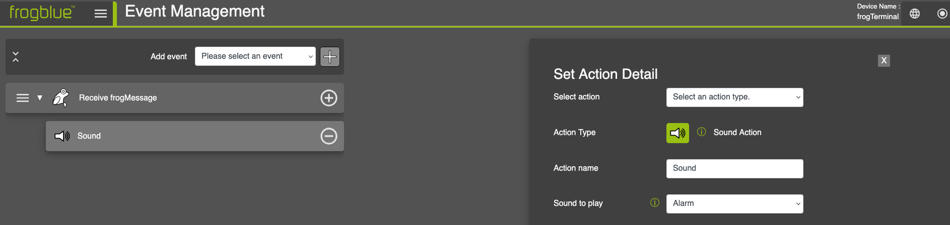
- Sound to play: Select the sound to be played from the dropdown menu.
9.2.10. Record Image Action
Starts image
recording.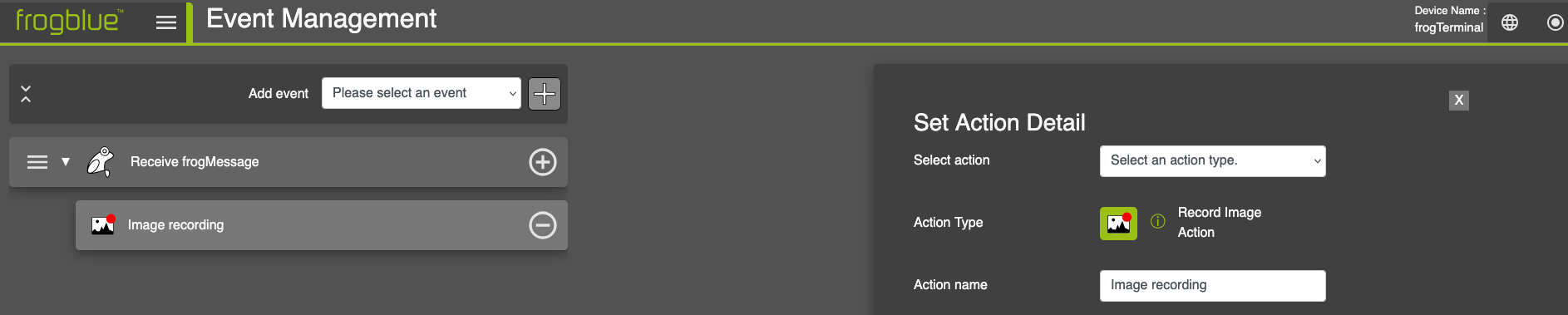
9.2.11. Store Variable Action
Stores a value in a variable for a fix period of
time.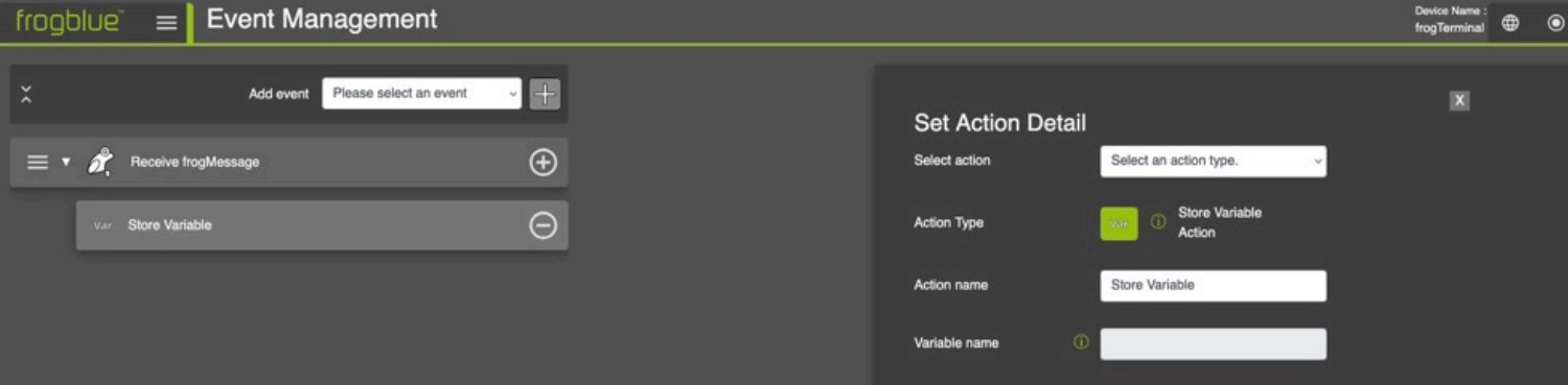
- Variable name: Enter a name for the variable.
10. Camera Settings and Recording Management
10.1. Configuring the Camera Image Settings
Via Web Browser Menu: Settings → Image Settings
Adjust camera settings for optimal video quality and coverage.
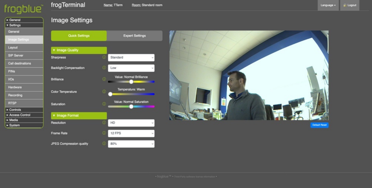
Image Quality:
-
Sharpness: Increases the clarity of edges and fine details, giving the image either a more defined, crisp or or a more smoothed look.
-
Backlight Compensation: Adjusts the intensity of the backlight to improve visibility in dark environments or to reduce glare in bright scenes.
-
Brilliance: Adjusts overall contrast and vividness, making colours and details stand out more.
-
Colour Temperature: Adjusts the warmth or coolness of the colours in the image, balancing the colour tones based on the environment (e.g., sunlight or fluorescent lighting).
-
Saturation: Controls the intensity of colours, allowing adjustments to make colours appear more vibrant or subtle.
-
Image Format:
-
Resolution: Determines the level of detail in the image and sets the clarity and pixel density of the video output.
-
Frame Rate: Controls or limits the number of frames per second, affecting the fluidity and smoothness of the video.
-
JPEG Compression quality: Quality setting for the underlying JPEG compression.
-
10.2. Optimal Settings for Low Latency & High Frame Rate
To achieve the best low-latency performance and high frame rate, ensure that:
No browser-based HTTPS or web stream is running (e.g., camera live stream in a browser).
The following image settings are applied:
Image Enhancement: Set to Off.
Image Resolution: Set to maximum HD.
JPEG Compression Quality: Set to 60%.
On-board recording is disabled for optimal performance. Instead, use a VMS system for video recording.
10.3. Event Recording Settings
Enable Configure manage event-based recordings.
Configure pre- and post-event snapshot settings.
Enable alert notifications for failed access attempts.
View and manage recorded events.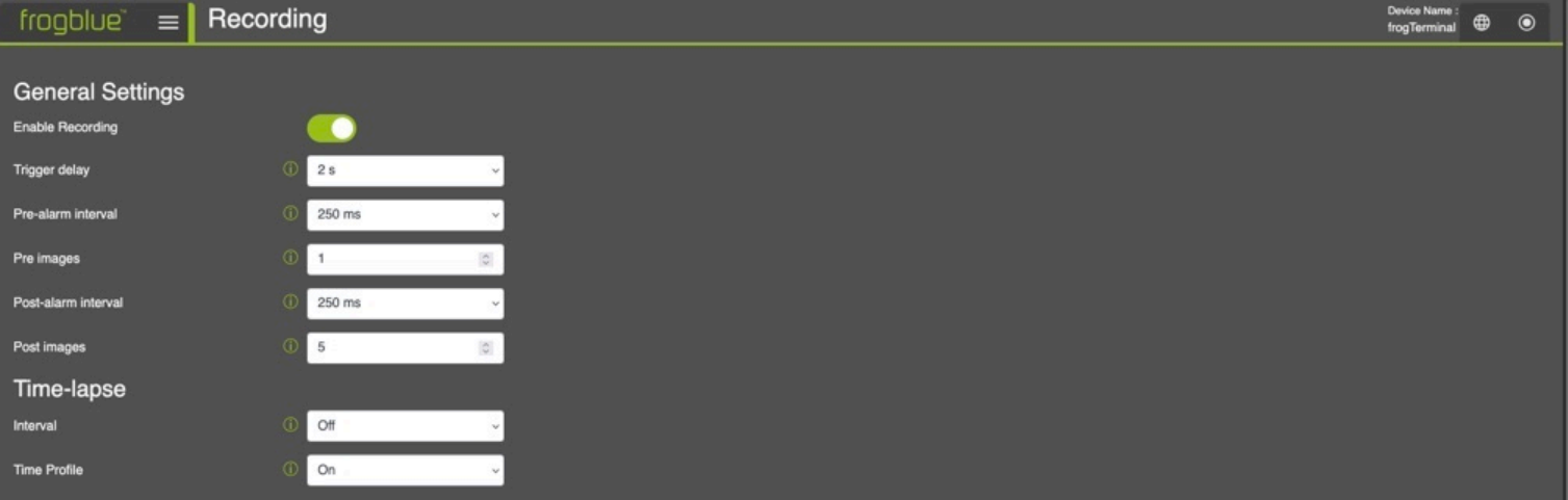
-
Enable Recording: Toggle event recording on or off for the on- board SD Card.
-
Trigger Delay: Set the delay between the event occurrence and the start of recording. This ensures that transient events, such as a bell press, do not capture an obstructive hand covering a significant portion of the image.
-
Pre-alarm Interval: Define the period during which recording occurs before the event is triggered. This interval, which includes the trigger delay, allows you to capture footage preceding the event.
-
Pre Images: Specify the number of images or frames to record prior to the event trigger.
-
Post-alarm Interval: Set the duration for recording after the event trigger occurs.
-
Post Images: Define the number of images or frames to capture after the event trigger.
-
Time lapse
-
Interval: Set the interval between time-lapse images to capture periodic snapshots.
- Time Table: Specify the schedule for time-lapse recording—for example, recording only during daylight hours—to ensure optimal image capture.
11. Function PINs
- Via Web Browser Menu: Controls → Function PINs
- Function PINs can be mapped to specific function allowing for example direct opening of a door, switching on all the lights in an area via frogMessage, or sending a silent alarm or security alert. Functions can be stacked much like with Call Destinations allowing for sequences or multiple actions e.g. open door but also trigger a silent alarm.
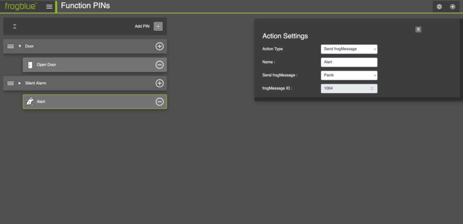
Function PINs: A function PIN must contain 1-6 numbers, the length of the PIN is freely selectable. Function PINs trigger stored functions, such as the local relay, or send messages via IP & Bluetooth
Note: Function PINs currently support sending frogMessages, triggering the built in relay, starting a door opener sequence, or sending IP messages or triggering 3rd party systems via HTTP msg.
12. Hardware
12.1. Proximity Sensor & Touchscreen Display
- Via Web Browser Menu: Settings → Hardware
- Configure the Terminal's wake up and standby setting.
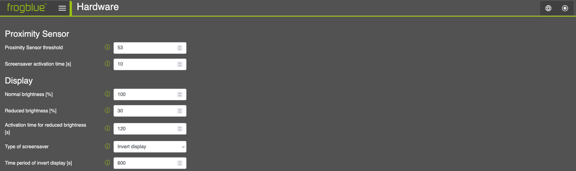
Proximity Sensor
-
Proximity Sensor threshold: This setting determines the sensitivity of the proximity detector, lower values mean higher sensitivity.
-
To visualise the current detection level, navigate through the device’s on-screen settings (
 →
→  →
→ 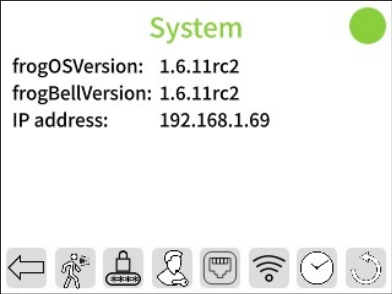 ) to view a live graph of the proximity sensor readings.
 -
Screen saver activation time: Time in seconds of no activity when the terminal will automatically return to the screen saver or Home Screen.
-
Display
-
Normal brightness [%]: This setting determines the brightness of the Terminal’s screen when activated e.g. by touch or proximity.
-
Reduced brightness [%]: This setting determines the brightness of the Terminal’s screen when in standby mode.
-
Activation time for reduced brightness [s]: Time in seconds after which the brightness is reduced and the Terminal is in standby waiting for a touch, movement, or other trigger to activate it.
-
12.2. Inputs & Outputs
Via Web Browser Menu: Settings → Hardware
Setup the hardware inputs and relay output settings for your frogTerminal.
Inputs (In a / In b): Configure the physical inputs A and B to
trigger actions based on state
changes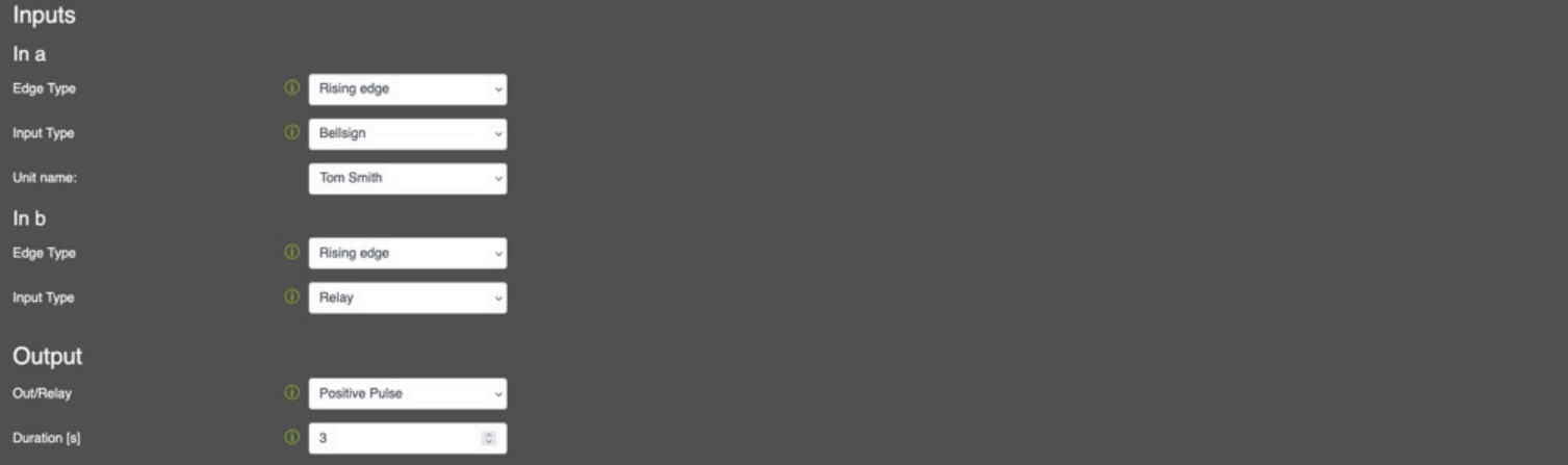
-
Rising edge: Activates when the input transitions from low to high.
- Falling edge: Activates when the input transitions from high to low.
Select the Action for the Input:
-
Bellsign: Choose the bell entry to trigger a call when this input is activated.
-
BT-Message: Send a Bluetooth message via frogMesh.
-
Relay: Activate the hardware relay.
-
IP Notify: Send an IP message or HTTP request to a specified URL.
-
Play Sound: Select an audio file (e.g., a bell sound) to play when the input is triggered.
-
Output: Set the physical relay output settings:
-
Out/Relay: Choose between a positive or negative pulse.
- Duration (s): Define the duration, in seconds, to trigger the relay.
13. Touchscreen Display Layout
- Via Web Browser Menu: Settings → Layout
- Configure the Home Screen Layout for the Terminals appearing on device touchscreen.
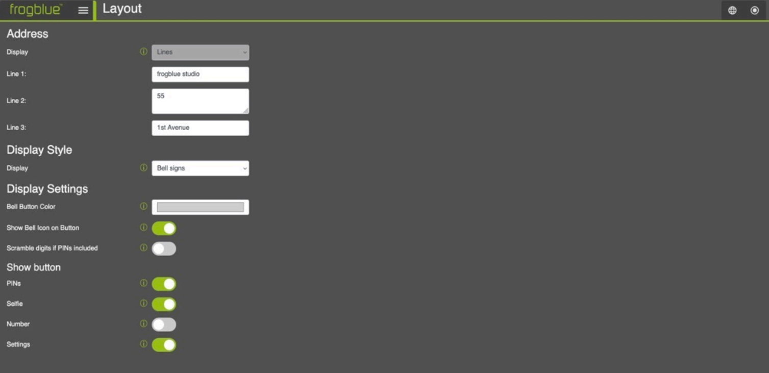
-
Address: The settings for the Standby Screen layout.
- Display: The settings for the Home Screen.
14. General Terminal Settings
- Via Web Browser Menu: Settings → General
- Configure general settings such as the name and default ring settings.
Settings
- Name for the doorVision: Enter the name for your frogTerminal i.e. Tom's Door to help identify the device within your system.
- Maximum ring duration: Set the maximum time the terminal will attempt to ring a callee before giving up.
- Maximum call duration: Set the maximum call time after which the terminal will automatically hang up.
- Show control icons during incoming call: Automatically display the toolbar when receiving a call (e.g., to enable or disable video).
- Max autoanswer level for users: Define the allowed level for automatic call answering:
- Decline: Automatically decline all incoming calls.
- - No: Do not allow incoming calls; no SIP connections will be accepted.
- Automatic answering: Enable automatic call answering. Note that individual user permissions must still be configured in the Call Destinations actions menu (click the \"i\" button next to a user's action entry to allow call answering at the terminal for that user).
- Allow callback shortly after missed ringing: After a call is missed, this feature permits the user or the called phone to call back and have the call automatically answered. It overrides other auto-answer settings and permissions.
- Sound on bell button press: The sound played at the Terminal when pressed on the bell button.
- Sound for incoming calls: The sound played at the Terminal when a call is made.
- Which sound on opening door: The sound played at the terminal when the door is opened - useful to alert the person the door is now open especially for silent door openers.
- Nightly reboot: Terminal restarts automatically between 2 a.m and 3 a.m.
15. Door Control Settings
- Via Web Browser Menu: Controls → Doors
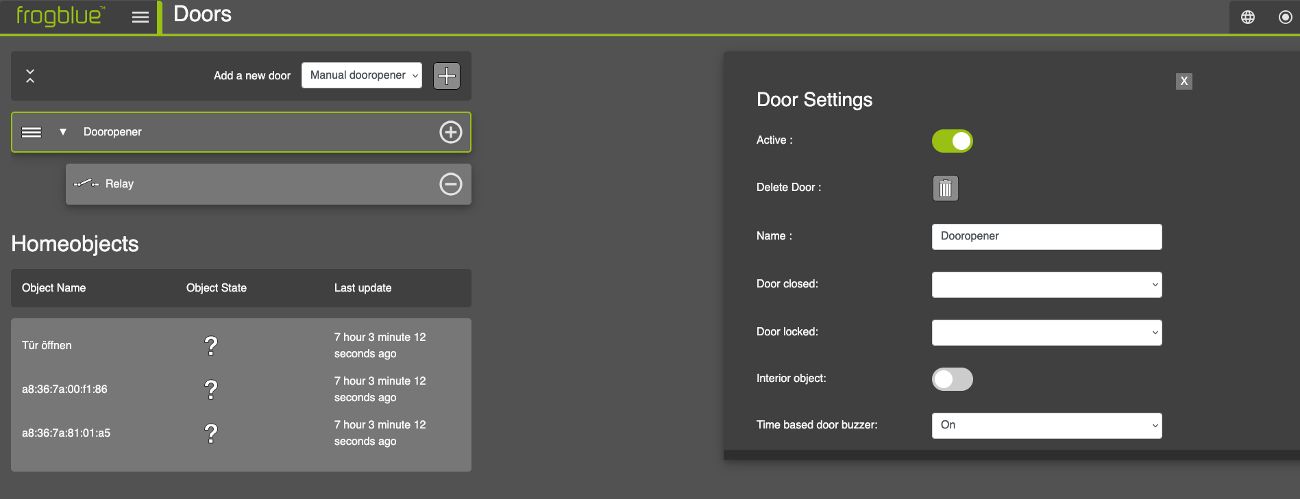
- Configure the local door opener, "Homeobjects" and the control options of the frogSip app.
16. On-board Media Settings
- Via Web Browser Menu: Media
- Upload and manage audio, image and video files and manage the recordings of local events.
16.1. Audio files
Allows managing and uploading custom audio files which can be used in the frogTerminal e.g. for custom bell sounds, voice or sound notifications or alerts.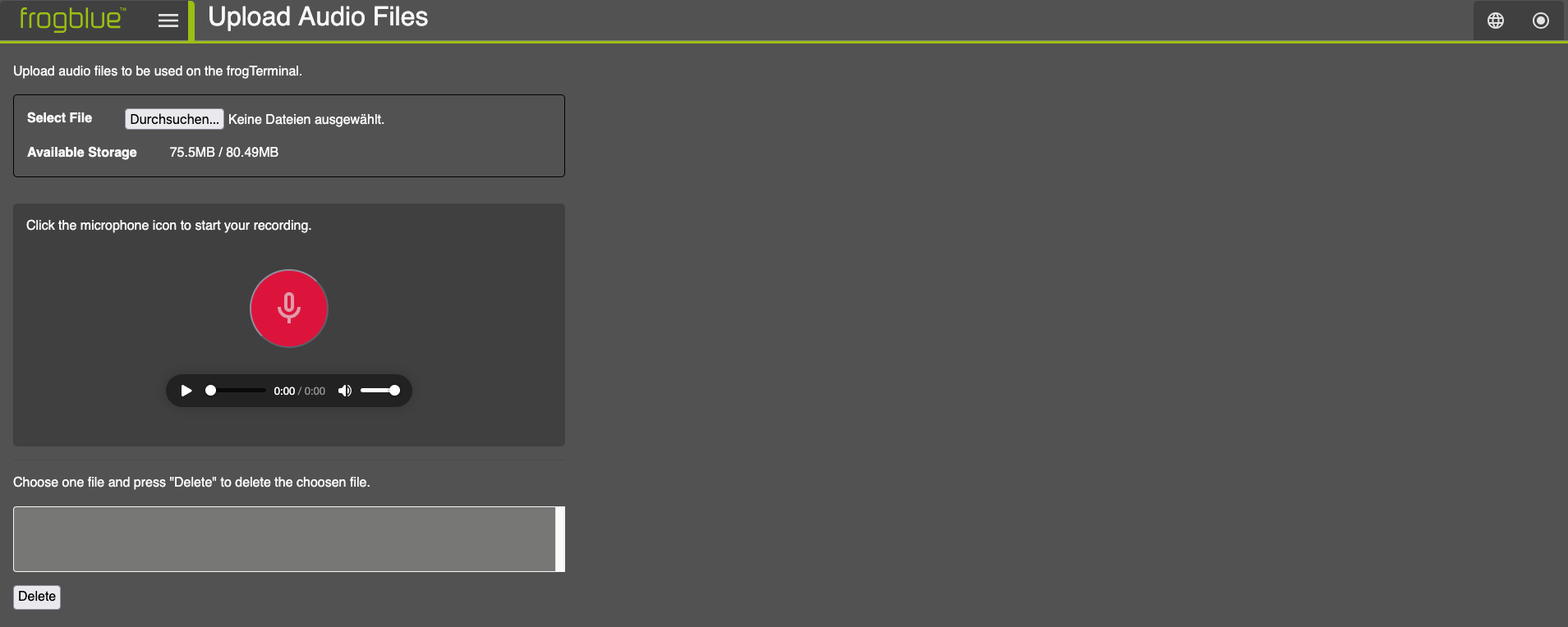
16.2. Image files
Allows managing and uploading custom image files which can be used in the frogTerminal e.g. for custom logos or user interfaces.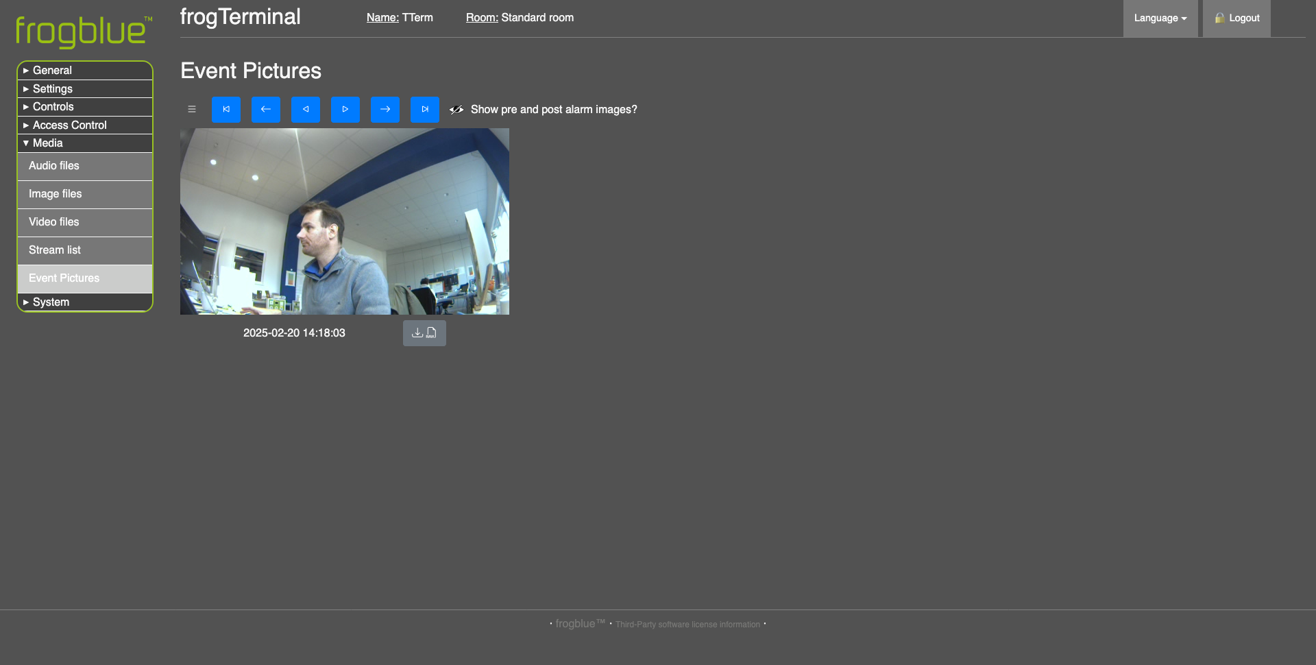
16.3. Video files
Allows managing and uploading custom video files which can be used in the frogTerminal e.g. for delivery instructions or automated site inductions.
16.4. Stream list
Feature not yet fully implemented - support for external streams coming.
16.5. Event Pictures
- Allows searching, viewing, and downloading stored event images from the frogTerminal.
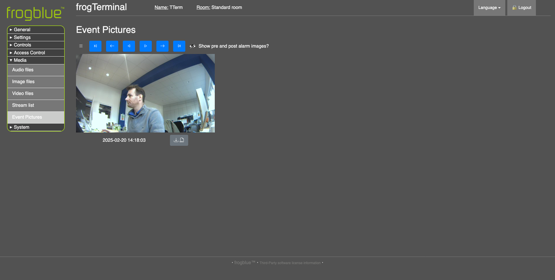
- Use the playback controls to find the event image you're looking for.
- Use the download button
 to download high quality RAW format images to your computer or browser enabled device.

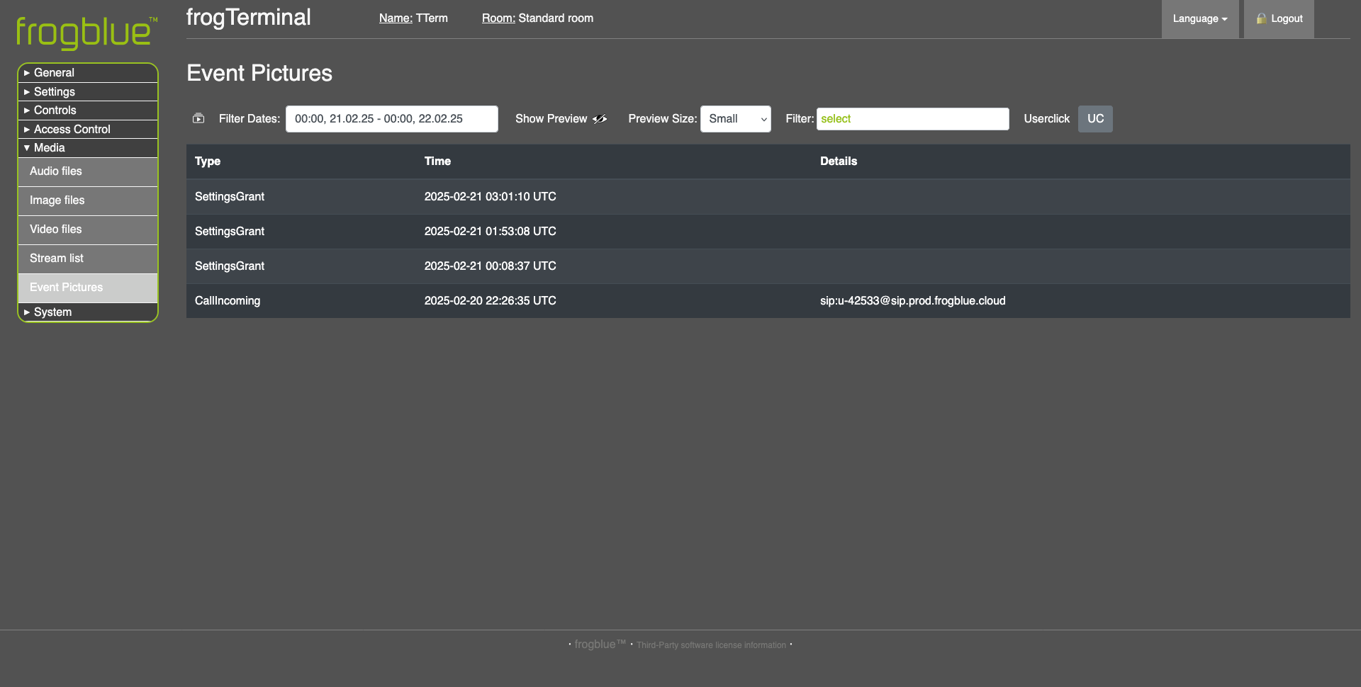
-
Use the event list view to search and filter events by Time, Date, and Event Type
-
triggers a manual recording.
17. Configuring the frogTerminal for Automation via frogCast/frogMesh
- Provisioning the frogTerminal with frogCast/frogMesh configuration enables seamless integration with frogBlue's smart automation mesh, allowing for automated control of lights, doors, and shutters.
- First note down your frogTerminals Bluetooth MAC-Address from Web Browser → General → Overview.
- Open the frogProject App on your iPad our compatible device.
- - Create a new Project and set the project password (for simple setup you can use the same password you set in 4.4 Installation Wizard Step 4: frogBlue Mesh Setup.
- If you left the interface open proceed. If you locked the interface see section 20 Maintenance and Troubleshooting on resetting your frogTerminal.
- Choose + to add a device to frogProject and search for your frogTerminal via the Bluetooth MAC-Address.
- Once added select your Terminal from the device list and hit the config icon to write the settings (Do not select any setting parts to be replaces simply tap OK)
- Your frogTerminal is provisioned and ready for automation. Steps where frogMessages are available i.e. in Function PINs or Call Destinations now show the available frogMessages in their respective drop down menus.
18. Network Configuration
18.1. Ethernet or Wi-Fi Setup
Configure the network settings to connect the frogTerminal to your local network.
Steps Overview:
- Choose connection type (Ethernet or Wi-Fi).
- Configure IP settings (DHCP or static).
- Test network connectivity.
18.1.1. Network Configuration Via Web Browser
- Menu: System → Network
- Not yet fully functional. Full Network setup via web browser coming soon via software update.
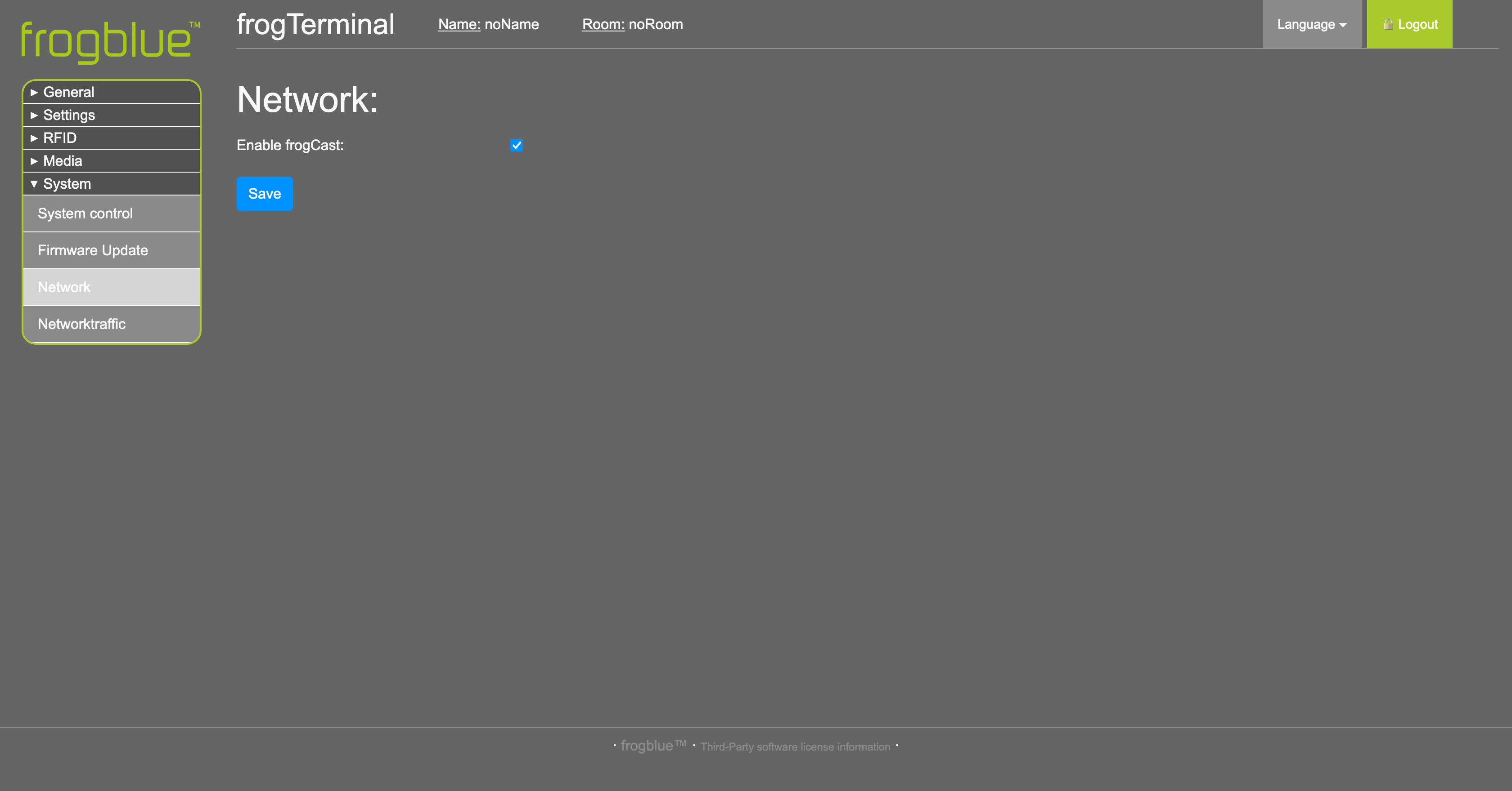
- Enable or disable frogCast via the checkbox.
18.1.2. Network Configuration Via On-Device Touch Screen
| Step | Description |
|---|---|
| 1 | Tap the settings icon to enter the configuration mode. |
| 2 | Enter your 6-digit Admin PIN and tap to confirm. |
| 3 | Tap the network icon to access the additional settings page. |
| 4 | Tap the Ethernet icon to configure Ethernet Settings (Jump to Section 4.1.7). Tap the Wi-Fi icon to configure Wi-Fi Settings (Jump to Section 4.1.7). |
18.1.3. Ethernet Configuration Via On-Device Touch Screen
| Step | Description |
|---|---|
| 1 | Leave active or deactivate Ethernet via the toggle switch if using Wi-Fi. Tap the lines to modify IPv4 address or DNS Settings. Tap the back arrow to return, or the save icon to save changes and return to the Network Setup Page. |
18.1.4. Wi-Fi Configuration Via On-Device Touch Screen
| Step | Description |
|---|---|
| 1 | Activate via the toggle switch if using Wi-Fi. Wait for the network list to populate (this may take a few minutes in complex setups). Tap on your preferred Wi-Fi Network or tap the manual entry icon to manually enter Wi-Fi details. |
| 2 | For manual setup, tap and enter Network Name, Password, and Security mode. For a Network selected from the list enter the Password & Security mode. Use the on-screen keyboard to enter the details and finally, tap Connect. If the first attempt fails, pause briefly and tap Connect again. |
18.1.5. Troubleshooting Network Connection Problems
Ethernet Connections:
Ensure all cables are securely connected and undamaged.
Test the Ethernet cable with another device to rule out cable issues.
Verify the network port is active and properly configured.
Wi-Fi Connections:
Move the device closer to the Wi-Fi router to improve signal strength.
Check for obstacles or interference, such as walls or other electronic devices.
Ensure the Wi-Fi credentials are entered correctly.
General Network Checks:
Restart your router or access point.
Verify the device is allowed on the network (e.g., MAC address filtering is disabled).
Contact your administrator to ensure settings are correct and no restrictions are in place.
18.2. SIP Server Registration
This section explains how to register the terminal with a Session Initiation Protocol (SIP) server for telephony and intercom functionality. SIP registration enables the terminal to make and receive calls, integrate with VoIP systems, and support video calls.
Steps Overview:
Single SIP server registration.
Multiple SIP server registrations (multi-tenant scenarios).
Testing SIP connectivity.
18.2.1. SIP Basics
Before proceeding with configuration, it’s useful to understand some key SIP concepts:
SIP Server (Registrar Server): The main server handling SIP registrations and authenticating devices. This is the primary server address where the terminal registers.
Outbound SIP Server (Proxy Server): A secondary server used for routing outbound calls, often different from the registrar server. Some providers require a separate outbound server for call handling.
SIP Account (Username & Authorisation Username):
Username (SIP Extension): The unique identifier assigned to the terminal (e.g., 1001 or door@mybuilding.com).
Authorisation Username: Some SIP providers require a separate authorisation username for login, which may differ from the SIP extension.
SIP URI (Uniform Resource Identifier): The terminal’s SIP address, formatted like an email (e.g., sip:door@mybuilding.com).
SIP Transport Protocols: The method used to send SIP messages:
UDP (fastest but less reliable)
TCP (more reliable, better for NAT traversal)
TLS (encrypted and secure, recommended for VoIP security)
SIP Video Support: If enabled, the terminal can transmit real-time video alongside audio calls using compatible codecs (e.g., H.264).
18.2.2. SIP Setup via Web Browser
Via Web Browser Menu: Settings → SIP Server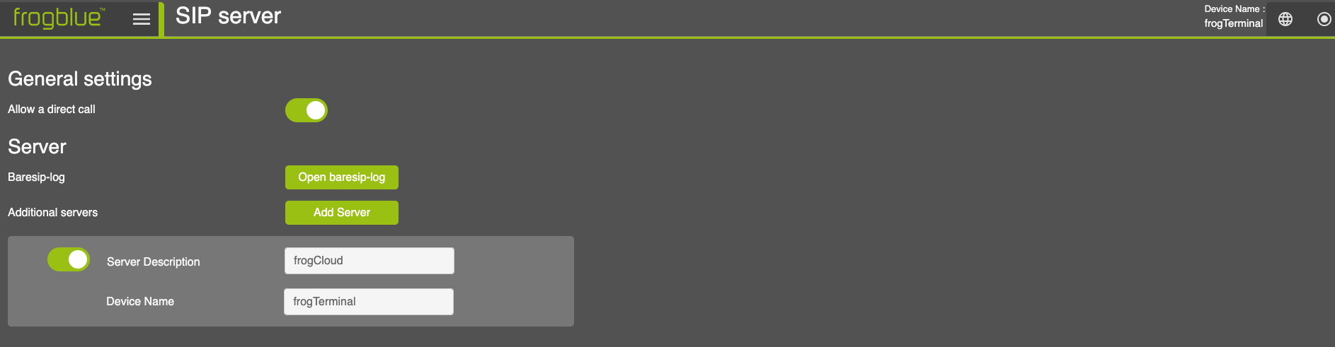
General Settings:
Allow direct call: Check/uncheck to allow/deny direct IP calls at this Terminal without requiring any authentication via a SIP Server.
Warning! INSECURE: For testing or local (advanced) usage only. Use with caution as may result in malicious calls or call hijacking.
Server:
Baresip-log: Open log file for expert debugging purposes.
Additional servers: Add a new SIP server. By default, the frogCloud is already integrated.
When clicking on Add server, the following dialogue
opens: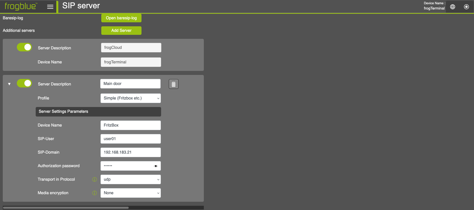
- Server Description: Name of the SIP server
Profile: Choose a profile from the dropdown menu
Device Name: Name of the SIP device
SIP-User: User of SIP device
SIP-Domain: IP adress of the SIP device
Authorized password: Passwort of the SIP device
18.3. Custom root certificates
- This section explains how to configure custom certificates on the frogTerminal for secure communication. The terminal allows you to upload a custom Root CA certificate, as well as a device certificate and private key in PEM format.
- This functionality is useful for environments requiring secure and private connections, particularly with internal networks or custom Certificate Authorities (CAs).
Steps Overview:
- Uploading a custom Root CA certificate.
- Uploading a device certificate and corresponding private key.
- Verifying certificate information.
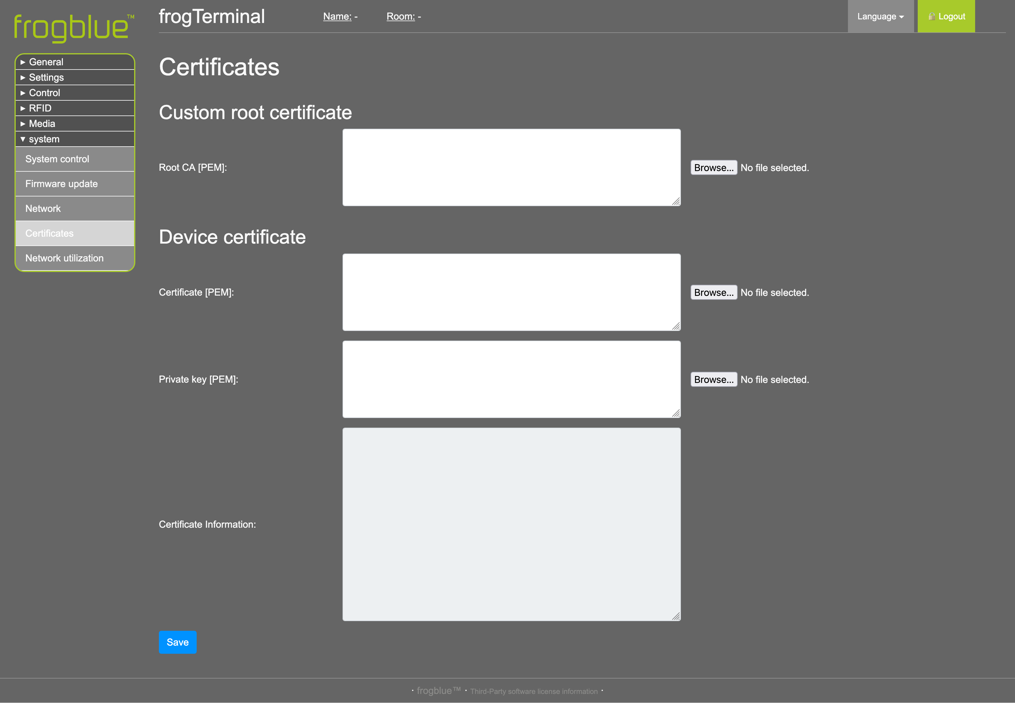
Custom Root Certificate:
The Root CA (PEM) field allows you to upload a custom root certificate in PEM format. This is used to authenticate server or peer certificates for secure communication. Use cases:
-
Integrating with private or internal CAs.
- Enabling secure API calls or encrypted communication in private networks.
How to upload:
-
Click Browse next to the Root CA (PEM) field.
-
Select the appropriate PEM file containing your Root CA certificate and click Open.
-
Click Save to apply your custom root certificate.
-
Device Certificate:
-
The Certificate (PEM) field allows you to upload the device’s unique certificate for identification and authentication.
- The Private Key (PEM) field allows you to upload the private key associated with the device certificate.
Use cases:
-
Secure mutual authentication with servers (e.g., in TLS handshakes).
- Enabling encrypted communication between devices and servers.
How to upload:
-
Click Browse next to the Certificate (PEM) field and select the device certificate file and click Open.
-
Click Browse next to the Private Key (PEM) field and select the private key file and click Open.
-
Ensure both files are correctly paired and valid.
-
Certificate Information:
-
The Certificate Information field provides a summary of the uploaded device certificate, including details such as the certificate’s issuer, validity period, and subject.
- Verify this information to ensure the certificate has been uploaded and recognised correctly.
Important Notes:
-
Ensure all files are in PEM format before uploading. Unsupported file formats will result in errors.
-
Uploading incorrect or invalid certificates may cause connectivity issues or disrupt communication.
-
For private networks or custom applications, consult your system administrator for the correct certificates.
-
Certificates and private keys must be securely stored and handled to prevent unauthorised access.
-
19. Security
Via Web Browser Menu: System → Security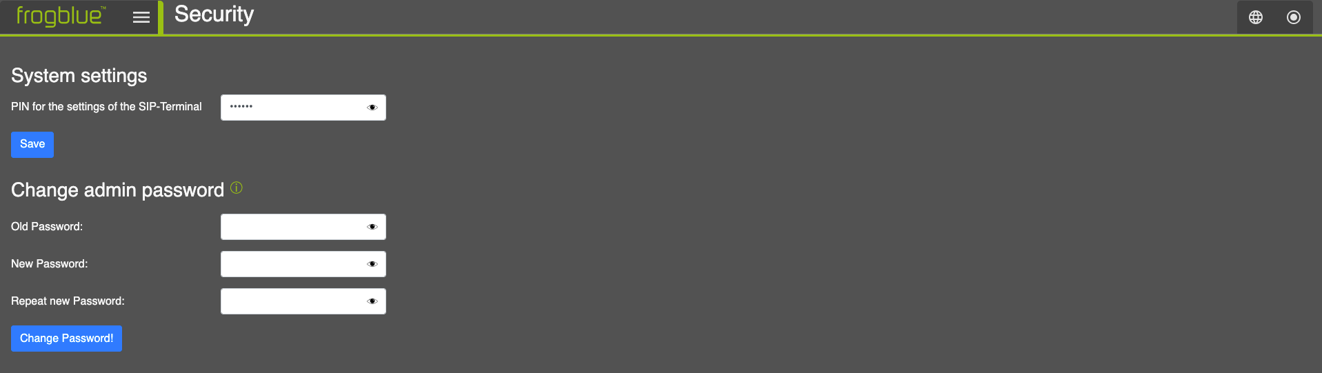
19.1. Admin PIN
PIN for the settings of the SIP-Terminal: Specifies an exact 6-digit PIN which is used to manage the frogTerminal via the on-device touchscreen to gain access to the local system settings.
19.2. Admin Password
Change admin password: Here you can change the web administrator password. Note you need to enter the old password and then twice repeat your desired new password before clicking Change Password!
20. Integration with Third-Party Video Systems
Integrate the terminal with external video streaming or management systems.
20.1. HTTPS or Web Integration - Plain MJPEG stream
The frogTerminal supports an MJPEG stream or Fast-Stream over HTTPS for compatibility with legacy systems or simple integration into websites. HTTPS authentication is required and can be passed in standard HTTP format, for example:
-
Basic URL: https://<IP Address>/cgi-bin/cam.cgi
- With Authentication: https://<username>:<password>@<IP Address>/cgi-bin/cam.cgi
20.2. RTSP Settings
Menu: System → RTSP Settings
The frogTerminal supports the Real-Time Streaming Protocol (RTSP) for integrating its camera video stream into third-party video systems. Audio support is currently in development.
RTSP is a widely adopted streaming protocol that allows clients to request, control, and receive real-time video feeds from IP cameras and media servers. It serves as the underlying protocol for ONVIF (Open Network Video Interface Forum), the industry standard for interoperability between IP-based security devices. ONVIF support for the frogTerminal is currently in development.
Many popular Video Management Systems (VMS), such as Milestone XProtect and Genetec Security Center, support direct RTSP stream integration, allowing the frogTerminal to be added as a video source without requiring additional drivers or plugins.
RTSP Stream URL Format
To access the RTSP stream from the frogTerminal, use the following URL format:
rtsp://<username>:<password>@<IP Address>:<port>/cam
-
<username>: The designated RTSP user (rtsp) or an admin user.
-
<password>: The password for the RTSP user or an admin account.
-
<IP Address>: The local or external IP of the frogTerminal.
-
<port>: The RTSP service port (default: 554, unless changed in the configuration).
-
/cam: The RTSP stream path.
-
Optimal Settings for Low Latency & High Frame Rate
To achieve the best low-latency performance and high frame rate, ensure that:
-
No browser-based HTTPS or web stream is running (e.g., camera live stream in a browser).
- The following image settings are applied:
-
Image Enhancement: Set to Off.
-
Image Resolution: Set to maximum HD.
-
JPEG Compression Quality: Set to 60%.
-
-
On-board recording is disabled for optimal performance.
- Instead, use a VMS system for video recording.
User Access:
-
The dedicated RTSP user (rtsp) can be used exclusively for RTSP streaming.
- Admin users can also access the RTSP stream using their credentials.
Additional Notes:
-
Ensure that RTSP is enabled on the frogTerminal and that firewall rules allow traffic on the specified RTSP port.
-
For remote access, port forwarding or a VPN connection may be required, depending on the network setup.
-
ONVIF support is planned, which will enable further integration with automated VMS discovery and additional video security platforms.
-
Latency and stream stability depend on network conditions and encoding settings.
-
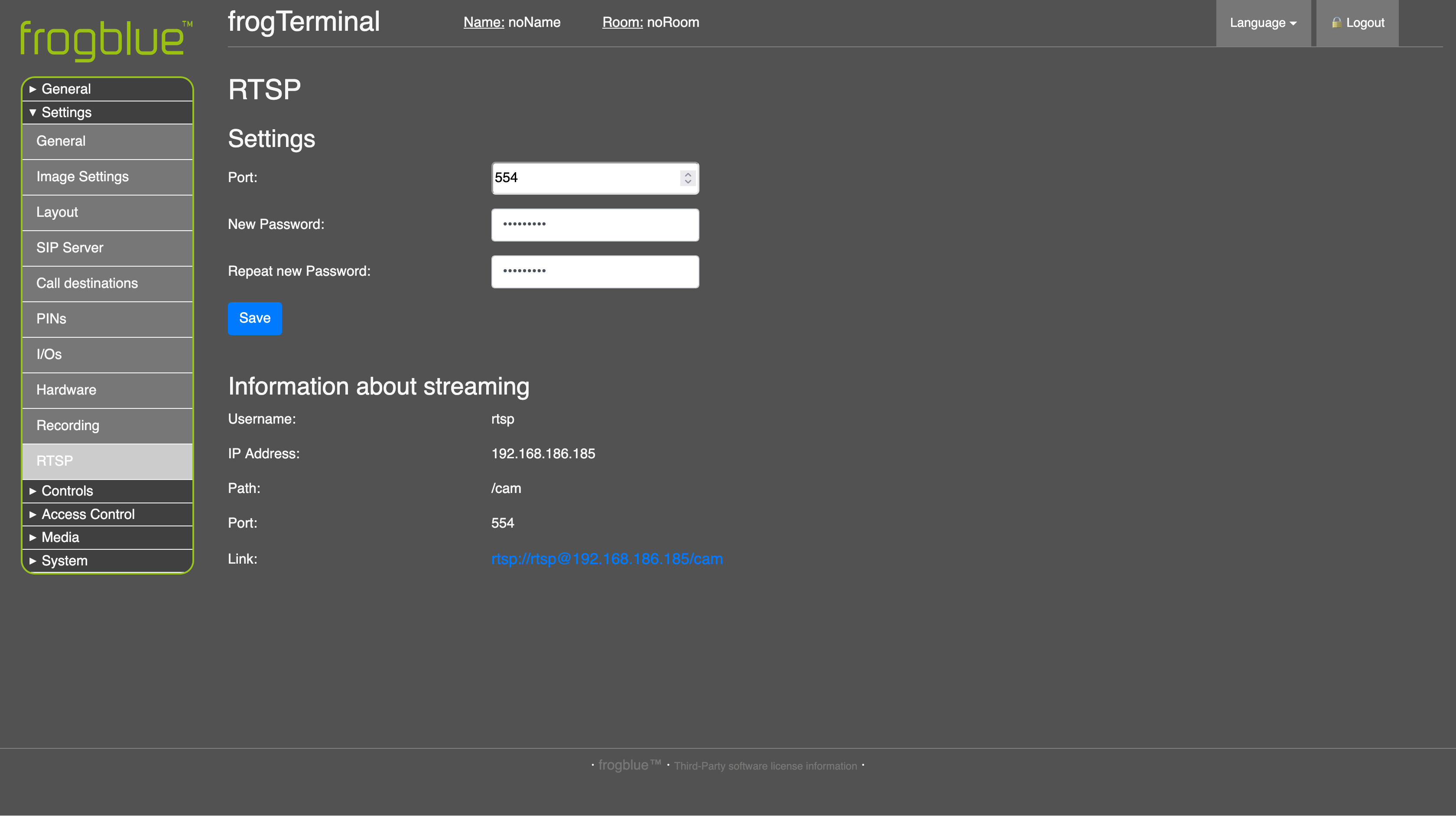
Port
-
Defines the port used for the RTSP streaming service.
-
Default: 554 (standard RTSP port).
-
If your network requires a different port, enter the desired custom port number.
-
Ensure that the selected port is open in your firewall/router if accessing the stream remotely.
-
New Password
-
Set a new password for the RTSP user (rtsp).
-
This is a dedicated password for connecting to the stream using the RTSP URL.
-
Minimum Requirements: At least 8 characters, including a mix of uppercase, lowercase, and numbers for security.
-
Repeat New Password
- Re-enter the new password to confirm it.
Save
-
Saves the updated port and password settings.
-
Changes will take effect immediately after saving.
-
After saving, update your RTSP settings in external applications if you changed the password or port.
-
20.3. RTSP Stream Integration
This section provides step-by-step instructions on how to integrate the frogTerminal RTSP stream with OBS Studio and VLC Media Player.
Ensure that:
RTSP is enabled on the frogTerminal.
The correct RTSP URL is used:
RTSP Integration with VLC Media Player
VLC Media Player is an open-source video player that supports RTSP streaming. To integrate the frogTerminal RTSP stream into VLC:
Open VLC Media Player.
- Click Open Media.
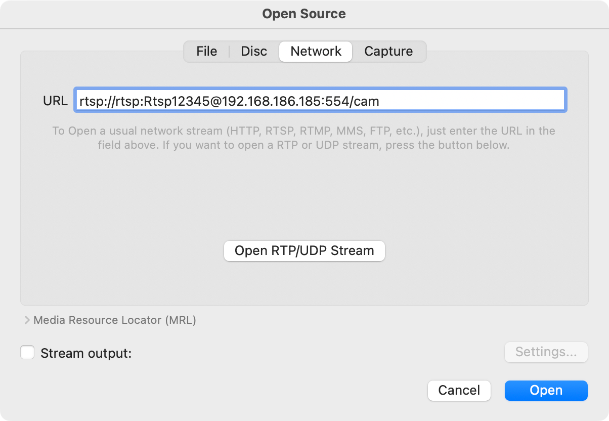
-
Go to → Network.
-
Enter the RTSP URL. The username and password can be passed in HTTP format as per the example or entered at the next step.
-
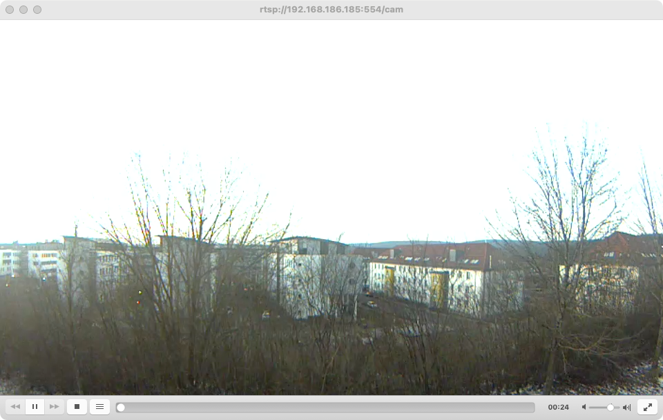
-
The camera stream should now appear in the VLC main window. By default, VLC will buffer the stream, which may introduce a delay of several seconds.
-
Note: VLC is primarily designed for streaming over the internet and includes built-in buffering mechanisms that may increase latency, which may affect real-time performance. To optimise VLC for low-latency streaming, adjustments to buffering settings may be required.
-
RTSP Integration with OBS Studio streaming and recording software
- OBS Studio is a widely used open-source streaming and recording tool. Follow these steps to integrate the
- frogTerminal RTSP stream into OBS:
- Open OBS Studio.
- Click + under Sources to add a new video source.
- Choose Media Source.
- Give your source a name i.e. "frogTerminal"
- Click OK
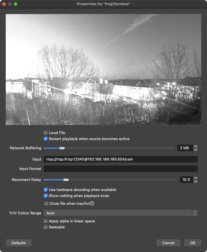
-
Untick Local File
-
Input: Enter the RTSP URL. The username and password can be passed in HTTP format as per the example or entered at the next step.
-
Tick Use hardware decoding when available
-
Click OK
-
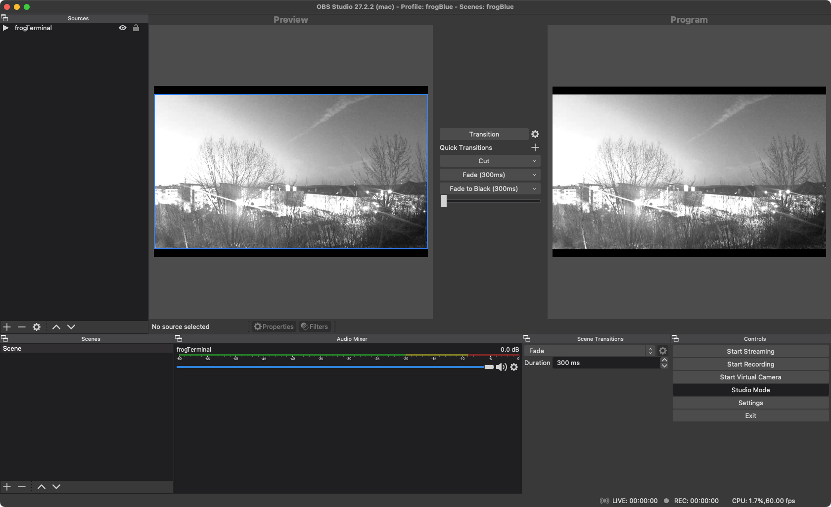
-
The frogTerminal camera livestream should now be visible in OBS Studio.
-
Note: On some operating systems or OBS versions, you may receive a popup window requesting permission to allow OBS Studio access to your network or through your firewall. Ensure that you confirm or
-
allow this access to enable the stream. Additionally, on certain systems, OBS Studio may need to be restarted after completing the setup and acknowledging any popups. If the stream does not appear immediately, try
-
closing and reopening OBS Studio.
-
20.4. Integration with MOBOTIX ManagementCenter (MxMC)
20.4.1. Overview
frogTerminal - MxManagementCenter
The frogTerminal offers functionality to support integration with MOBOTIX MxManagementCenter Software. Supported Version: MxManagementCenter 2.9.2 Protocol: MxEventStream via Port: 8035
Features supported by the frogTerminal include:
-
Video & Audio Stream (MJPEG)
-
Calls from frogTerminal to MxMC (MxMC Background Alarms)
-
Live video call pop-up
-
Two-way audio (push-to-talk)
-
Open Door
-
Switch on Light (Feature otw.)
-
-
Event Image review from MxMC Event Strip (Right Sidebar)
- Advanced MxMC button integration via API (IP Messages / WebHooks)
Supported applications include, Door Terminals, Call Stations, Help or Information Points with the integrated touch display and API support enabling advanced users the ability to customise the applications even further.
- frogTerminal - as IP gateway to frogblue automation system.
The frogTerminal offers functionality to support integration with IP based systems.
- frogDisplay - as IP Call Station for MOBOTIX door station system.
The frogDisplay offers functionality to support integration with MOBOTIX door station systems: T24, T25, T26 and can be called as an endpoint for door bell events triggered via the MOBOTIX ‘Concierge’ system.
- MOBOTIX Camera Device - as IP gateway to frogblue automation system.
The frogTerminal offers functionality to support integration with IP based systems.
20.4.2. Integration Step by Step
| Step | Description |
|---|---|
| 1 | Click on the Lock Symbol at the bottom of the left sidebar to unlock the interface. |
| 2 | Click on the + symbol at the bottom of the left sidebar to add a new device element. |
| 3 | Click on the Manually symbol to add a new camera source. |
| 4 | Name: Enter a name for your frogTerminal as it should appear in MxMC. Connection Protocol: Select MOBOTIX from the options. URL: Input the IP Address or URL of your frogTerminal followed by a colon and the port 8035 (e.g. 192.168.178.58:8035). User Name: Input the web username to access the frogTerminal. Password: Input the web password. |
| 5 | If you see a Security Alert click Always Trust to accept the secure connection. Or for temporary testing choose Trust this Time. |
| 6 | You should see a live video stream from your frogTerminal in MxMC. |
| 7 | If the connection does not establish: Click the Reconnect button (refresh icon in the top-right corner). Accept any Security Alerts that appear. If issues persist, check your network settings. (This port is used for the MOBOTIX MxEventStream protocol.) |
Add frogTerminal to MxManagementCenter
To add the frogTerminal as a device to the MOBOTIX
MxManagementCenter Software open your MxMC Version
2.9.2.
- frogTerminal - calls to MxManagementCenter
| Step | Description |
|---|---|
| 1 | Click and select Notify MxMC as the call action. |
| 2 | Add a Bell sign or select an existing Bell sign to use and click the + icon to expand the call action settings. Click the + icon to add a call action. |
| 3 | Action name: Enter a name for the action (e.g. Notify MxMC Station 1). MxMC IP: Enter the IP Address of the computer where the MxMC Software is installed. Click Create to finish creating your action. |
The frogTerminal offers functionality to call MxManagementCenter Software directly via the MxEventStream protocol.
To configure a call to your MxMC you will need the IP Address of the computer where the MxMC Software is installed then open a browser to your frogTerminal to the Settings -> Call destinations page.
Tip: Calls can also be made directly to the frogTerminal from MxMC by clicking on the phone icon while connected to the frogTerminal live-stream.
| Step | Description |
|---|---|
| 1 | A call is initiated and should appear in MxMC. The door icon directly triggers the frogTerminal door opener as defined under the Controls > Doors settings. The green phone icon lets you accept the call. |
| 2 | Once in a call: To Speak - Press and hold the green call icon. To Open the door - Click the door icon to trigger the door. To switch the light - Click the light icon to trigger the light. To end the call - Click the red phone icon. |
Tap your newly created Bell sign i.e. "MxMC" from the frogTerminal
touchscreen bell
page.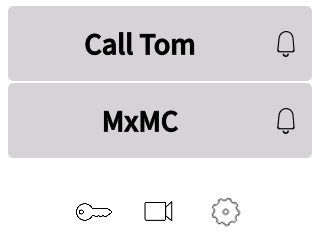
- frogTerminal - event review with MxManagementCenter
The frogTerminal offers basic image event review from MxMC.
To review events click to open the right event-strip sidebar in MxMC.
| Step | Description |
|---|---|
| 1 | Click on an event image to inspect it in full screen. |
21. Advanced Integration and API Features
Note: Special Features! Talk to your frogblue Partner or local frogblue Competence Center for details.
21.1. Custom Display Interfaces
Customise your frogTerminal's user interface to achieve stunning designs and next-level integrations. This high-quality smart door station access control interface is the ideal solution to elevate your system or SaaS offering, delivering both enhanced aesthetics and advanced functionality.
21.2. Time Tracking and Attendance
Leverage the frogTerminal to streamline staff time tracking. Configure simple check-in, break, and check-out options, and export attendance logs to your preferred workforce management system for efficient record-keeping.
Examples applications include:
- Logistics: Notify warehouse automation systems to prepare or dispatch an order upon access. Automatically light a path to the delivery gate for efficient navigation.
- Healthcare: Trigger nurse call or management systems to log patient visitor details or confirm the delivery of critical medication including QR code verification to ensure the right medication is given to the right person.
- Building Automation: Activate lighting and adjust HVAC settings along a defined route for the user, or automatically call an elevator to the correct floor.
22. Maintenance and Troubleshooting
22.1. Firmware Updates
Keep the terminal up to date with the latest features and security patches.
22.2. System Control - Manage configuration files, Reboot, and Factory Reset
This section details how to download or upload the entire configuration, reboot the system, or reset the device to factory defaults.
Reset system to factory defaults via Web interface
Menu: System → System Control
To perform a factory reset, click \"Reset to Factory Defaults\" and then \"Yes\" to confirm. Wait until you see the message \"Done\" in the browser and the Terminal screen returns to the Welcome page with the Start Wizard option. Please note that the reset process may take several minutes to clear all logs and recordings. For best results, allow sufficient time and perform a reboot or power cycle after the reset.
Via On-screen interface
| Step | Description |
|---|---|
| 1 | Tap the settings icon to enter the configuration mode. |
| 2 | Enter your 6-digit Admin PIN and tap to confirm. |
| 3 | Tap the settings icon to access the additional settings page. |
| 4 | Tap the reset icon to enter the system reset and reboot menu. |
| 5 | The Home Screen defines the standby view. Tap to set your text for each of the lines. Tap “Preview” to view your setup. Tap the next arrow to proceed. |
Note: A hard reset can be performed with the frogProject App when all PINS & Passwords forgotten. Reach out to your frogblue Partner or local frogblue Competence Center for support.